
Manual


29
3. Installation and Wiring
3.10 Connecting the I/O Shield Cable
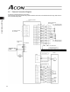
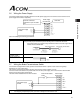
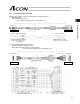
Cable model: CB-PACPU-PIO***
(Note: *** indicates the cable length. (Example) 2 m: 020)
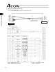
Pin No. Color Name Remarks
1 Black External 24 V
2 White/Black External ground
If the controller is used in the open collector mode, also use this pin
for the COMMON signal for command pulses.
3 Red SON Servo-on signal
4 White/Red TL Torque-limit selection signal
5 Green HOME Homing signal
6 White/Green RES/DCLR Reset signal/deviation-counter clear signal
7 Yellow SV Servo-on output
8 White/Yellow INP/TLR Positioning complete signal/torque limit signal
9 Brown HEND Homing complete signal
10 White/Brown *ALM Alarm signal
11 Blue Command pulse/PP
12 White/Blue Command pulse PP Not connected if the controller is used in the open collector mode.
13 Gray Command pulse/NP
14 White/Gray Command pulse NP Not connected if the controller is used in the open collector mode.
- - FG Shield (connected to the enclosure)
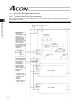
No connector
Housing
Contact
Shield cable
Round
terminal