
Owner's manual

20
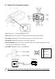
7. Network Port: Used to connect a PoE or LAN cable. Power indicator (Green LED) will be on
when connect with the PoE Hub; the Orange LED will be flash when plug the communication is
available.
8. Audio Out: The terminal block is connected the speaker to output voice.
9. Audio In: The terminal block is connected the microphone for audio signal input.
10. Rest: Press and release the recessed reset button with a straightened paper clip.
11. Micro SD Slot: Inserts SD card for video/snapshot recording. Max.64GB SDHD card supported.
12. Antenna: For WI-Fi Antenna adapter (Revised).
13. Power Indicator: The LED will be on when plug the DC 12V power adapter or POE Hub.
14. USB Port: Used to Wi-Fi adapter (Revised).
15. Terminal Block: See the pin define as below:
Alarm Out: Digital output (1A/1B); Connects to external peripherals by wire
Alarm In: Digital input; Accept dry contact signal only.
Ground: Common port where the alarm in signal is connected.
RS-485 (-)/ (+) : RS-485 control port for the Pan/Tilt motor . The protocol supports Pelco P
and Pelco D.
16. BNC Port: Composite Video output.
17. Power Port: Used to plug the DC 12V power adapter when no use PoE Hub.