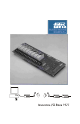
Basic I/O Product Family NOTICE: This document contains two separate users manuals. The first section should be used for the BIO4, BIO8, and BIO16 products. The second section should be used for the BIO4AD, BIO8AD, and the BIO16AD products. If you find that you have any questions with the setup or installation of any duTec product please feel free to call us: Phone: 800-248-1632 or E-mail: info@dutec.
Vol.1 Table of Contents The Basic I/O . . . . . . . . . . . . . . . . . . . . . . . . . . . . . . . . . . . . . . . . . . . . . . . . . . . . . . . . . . . 1 - 1 ANALOG INPUTS . . . . . . . . . . . . . . . . . . . . . . . . . . . . . . . . . . . . . . . . . . . . . . 1 - 2 DIGITAL INPUTS . . . . . . . . . . . . . . . . . . . . . . . . . . . . . . . . . . . . . . . . . . . . . . . 1 - 4 DIGITAL OUTPUTS: . . . . . . . . . . . . . . . . . . . . . . . . . . . . . . . . . . . . . . . . . . . .
Vol. 1 Table of Contents Communication verification . . . . . . . . . . . . . . . . . . . . . . . . . . . . . . . . . . . . . . . . . . . . . . . 2 - 18 Hardware error codes . . . . . . . . . . . . . . . . . . . . . . . . . . . . . . . . . . . . . . . . . . . . . . . . . . . . 2 - 19 Hardware watchdog . . . . . . . . . . . . . . . . . . . . . . . . . . . . . . . . . . . . . . . . . . . . . . . . . . . . . 2 - 19 Sensor/ Actuator I/O wiring . . . . . . . . . . . . . . . . . . . . . . . . . . . . . . . . .
The Basic I/O 1 THE BASIC I/O: BASIC I/Os are a family of small, industrial grade, remote data acquisition and control systems which exchange data with a Host computer via a serial communications link. Controlled by a wide range of software running on a Host computer, Basic I/Os are located near the sensors and actuators. The serial link eliminates the need for expensive and noise prone signal wiring between field sensors and actuators, and a central control room.
The Basic I/O 1 A notable feature of the BASIC I/O is its ability to gather data and perform ranging and statistical operations on raw data before it is sent to the Host. The Host can thus spend less time manipulating data and more time gathering it. The following sections discuss the different signals the BASIC I/O can handle. ANALOG INPUTS: duTec analog input modules are 100% isolated and accept a wide range of voltages, currents, the outputs of thermocouples, RTDs, and 590 type temperature probes.
The Basic I/O 1 ANALOG OUTPUTS: Analog output modules are 100% isolated. These self-sourcing modules provide the voltage or current necessary to drive standard instrumentation loads. All are updated every 10 Ms, or 100 times per second. Analog output instruction types are: Level Value Can set output levels, as a fraction of the module’s full scale range, and are specified with 12 bit (1 part in 4096) resolution.
The Basic I/O 1 DIGITAL INPUTS: Digital input modules detect the presence or absence of a field signal. Module types vary from AC to dry contact sense. Because the industry standard modules are optically isolated, the response time performance of digital input instructions can be limited by the delay in the input modules themselves. Some modules can have rise and fall times of up to 40 milliseconds. Digital input instruction types are: Read Read the On or Off state of all inputs.
The Basic I/O 1 DIGITAL OUTPUTS: Digital output modules, commonly referred to as solid state relays, control external AC or DC power sources. A dry-contact (mechanical relay) with very low contact resistance is also available. Digital output instruction types are: Set outputs Can set individual or multiple outputs On or Off. Pulse Generator Modifiers: One Shot Can generate 1 to 65,535, 50% duty cycle pulses whose equal On and Off periods can range from 0.01 to 2.55 seconds.
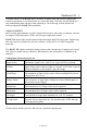
The Basic I/O 1 SYSTEM THROUGHPUT: Input data throughput is the time from beginning of the first character of an input instruction to the end of the last character of the response. The processing time of the Host computer will affect the effective throughput. Output Execution throughput is the time from the beginning of the first character of an instruction until the actual output changes.
The Basic I/O 1 It should be noted that the values in the preceding throughput tables and the following equations reflect only the communications overhead and inherent processing delay of the BASIC I/O equipment. In practice, a significant amount of overhead will be devoted to other processing tasks such as screen updates, Data logging, etc... Typically these other tasks become the limiting factor in the “overall” throughput.
The Basic I/O 1 COMMUNICATION PROTOCOL: The BASIC I/O Communication Protocol is 100% compatible with the Opto-22 Optomux™ protocol. This ASCII printable serial protocol uses a “speak-only-when-spoken-to” format where only the host can initiate an information exchange. Each BASIC I/O unit installed in a network has a unique address. This address is embedded in the instruction generated by the host computer.
The Basic I/O 1 Available I/O Modules ANALOG INPUTS, 12 BIT ANALOG OUTPUTS, 12 BIT Voltage Frequency IIF10K-B Input 300Hz -10KHz OV1 Output 0-1V, self-sourcing IF2.5K-L IF5K-l Input 0-2.5KHz Input 0-5KHz OV5 OV10 Output 0-5V, self-sourcing Output 0-10V, self-sourcing IF10K-L Input 0-10KHz IV25M Input 0-25mV OI420 Current Output 4-20mA, self-sourcing To 275 Ohm load.
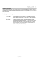
The Basic I/O 1 DIAGNOSTICS: To confirm internal operations and communications link integrity, a set of built-in diagnostics test key system functions each time power is applied. Diagnostics reduce both installation debugging and operation troubleshooting. A hardware watchdog timer insures safe shutdown in the event of processor or software failures by turning all outputs OFF. Normally ON modules are available for those loads that must remain ON. PHYSICAL CHARACTERISTICS Power Requirements Voltage: 5.0-5.
The Basic I/O 1 PRODUCT TEST Every BASIC I/O is burned-in at 70 °C while operating in a network for a period of 24 hours prior to shipment. Every analog I/O module is operated and tested while it’s ambient operating temperature is cycled over the specified operating range of 0°C to 60°C for a period of 24 hours. BASIC I/O Models: BIO4 4 Position BASIC I/O Unit Includes SLB Logic Board and SMB4 Module board less modules and power supply.
The Basic I/O 1 NOTES 1-12(Vol.
Setup & Installation 2 MOUNTING: BASIC I/Os come in 4, 8, and 16 channel versions. Figure 2-1 below shows the footprint of each BASIC I/O. Using corner holes, the unit can be mounted with 4- #6 or #8 round head or pan head screws. The BIO16 version has two additional mounting holes located near the center of the board as well. Hole locations in relation to the overall dimensions for each are shown below.
Setup & Installation 2 POWER WIRING: Power connections are made at the 2 position terminal block located on the module board marked +5V and GND No. 8 captive wire clamps accept 10-16 AWG wire or spade lugs. +5V GND Power wiring conventions: + of the power source to the +5V terminal - of the power source to the terminal marked GND Power requirements Voltage: Current: 5.0- 5.4Vdc 250 mA + 25mA per digital module or 250 + 200mA per analog module.
Setup & Installation 2 COMMUNICATING WITH THE BASIC I/O: The BASIC I/O is designed to serve as an intelligent I/O front end for a Host computer (Typically a P.C.). The host and BASIC I/O communicate over a serial link. This interchange is half-duplex in nature; that is to say the host and BASIC I/O will never be transmitting at the exact same time. Further, the communications protocol is considered “speak-only-whenspoken-to”; the Host must poll the BASIC I/O whenever it needs fresh data.
Setup & Installation 2 BASIC I/Os can be networked together to obtain up to 4096 I/O points of data. These serial networks can be either multidrop or repeat. Figure 2-3 Multidrop V.S. Repeat networks Multidrop: Multidrop networks can be up to 5000 ft long end-to-end. Each station is passively located on the network and represents one “Drop” or load to the host communication driver. A multidrop network will tolerate loss of power to any one station without effecting the rest of the network..
Setup & Installation 2 The serial communications link between a Host computer and a network of BASIC I/Os is made up of either a single (RS-485 half-duplex) or Dual (RS-422 full duplex) shielded twisted pair (s) of wires whose shields are connected to a signal common conductor. This communications link should in turn have an overall shield which is isolated from the signals (including signal ground) and connected to earth or chassis ground at one location.
Setup & Installation 2 RS-485 Programming: The BASIC I/O will work equally well when connected to either RS-422 or RS-485. However special host programming considerations may be necessary when implementing an RS-485 network. Unlike RS-422 where both the transmit and Receive signals have their own differential pair of conductors, RS-485 utilizes only one differential pair. The single pair of conductors is used bidirectionally and handles both transmit and receive signals.
Setup & Installation 2 approximate time necessary to transmit the entire instruction before the RS-485 driver is disabled. Since the BASIC I/O can respond very quickly to the instruction, the Host must disable the driver as soon as possible in order to receive the BASIC I/Os response. RS-485 communications can be tricky at best and should be seriously considered before being adopted.
Setup & Installation 2 Network load V.S. Noise suppression: In order to improve RS-485 Bus noise immunity, particularly under tri-state conditions, a pair of “Network Bias Resistors” have been installed in each BASIC I/O unit. This design feature has been implemented in order to satisfy the majority of our customers.
Setup & Installation 2 RS-422 HOST TO BASIC I/O: Figure 2-5 RS-422 Host to BASIC I/O wiring Figure 2-5 shows two individually shielded twisted pairs of AWG 24. Each pair has a ground wire connected to its shield. These drain wires are then connected to the signal grounds at each unit. A Separate shield encases the entire cable. The drain wire for this over-all shield is tied to earth ground at one location. An example of acceptable wire for this application would be Belden 8162.
Setup & Installation 2 BASIC I/O TO BASIC I/O RS-422 MULTIDROP OR REPEATER Figure 2-6 RS-422 BASIC I/O-To-BASIC I/O multidrop Figure 2-6 shows two individually shielded twisted pairs of AWG24. Each pair has a drain wire connected to its shield. These drain wires are then connected to the signal grounds at each unit. A separate shield encases the entire cable. The drain wire for the over-all shield is tied to earth ground at one end. An example of acceptable wire for this application would be Belden 8162.
Setup & Installation 2 RS-485 Host to BASIC I/O: Figure 2-7 RS-485 To-BASIC I/O Figure 2-7 shows one individually shielded twisted pair of AWG 24. Each pair has a drain wire connected to its shield. These drain wires are then connected to the signal grounds at each unit. A separate shield encases the entire cable. The drain wire for the over-all shield is tied to earth ground at one end. An example of acceptable wire for this application would be Belden 8162.
Setup & Installation 2 BASIC I/O to BASIC I/O RS-485 (Multidrop only): Figure 2-8 RS-485 BASIC I/O to BASIC I/O Multidrop Figure 2.8 shows one individually shielded twisted pair of AWG 24. Each pair has a ground wire connected to its shield. These drain wires are then connected to the signal grounds at each unit. A Separate shield encases the entire cable. The drain wire for this over-all shield is tied to earth ground at one location.
Setup & Installation 2 BASIC I/O setup: BASIC I/O setup is accomplished with a sequential display and pushbutton. Below is a diagram of the location of these components.: Figure 2-9 BASIC I/O Connectors, Switches and Indicators. Unit type (digital or analog), Unit address, baud rate, and 2 or 4 pass protocols are all pushbutton configurable and appear on the sequential display.
Setup & Installation 2 Analog/ Digital: The BASIC I/O system must be configured to accept either Analog or Digital I/O modules. The current I/O type is displayed on the sequential display and is indicated by the character following the “U”. The unit will display a”1" if the unit is configured as digital and a”2" if the unit is analog. This value is stored in EEPROM and need only be set once. The factory default I/O type is digital.
Setup & Installation 2 Protocol Handshake Types: Two protocol handshake types are available, 2 pass and 4 pass. 2 Pass: The host transmits an instruction to a BASIC I/O. If the instruction is correctly received (i.e. valid address, instruction type and correct checksum) the BASIC I/O executes the instruction and returns the letter “A” and a cr or, where data is to be returned, the letter “A”, then the data, followed by a two character checksum ending with a cr.
Setup & Installation 2 Network Type Switch: Based upon the selected network configuration, each BASIC I/O must be setup before communications can begin. This is done with the network switches shown below. The three basic communication connections for individual BASIC I/Os are: L1 Repeater Used in RS-422 networks to extend range to5000 feet between units L2 Multidrop Used in RS-422 or RS-485 networks. Provides a total network range of 5000 feet.
Setup & Installation 2 Setup via Pushbutton: The pushbutton, located on the logic board (see figure 2-9) is used to configure the unit address, baudrate, and network pass type. During the diagnostic test period following the application of power, the sequential display shows “GO GO GO GO GO/ “ Pumping the pushbutton once while the/ appears, places the unit in the setup mode. The BASIC I/O then flashes: U100 H096 P2 The underlined values represent setup parameters that can be changed.
Setup & Installation 2 Communication verification: Network Debugging: Most startup problems are related to the communication link. The installer is urged, after both the communications wiring and configuration have been completed, to test the network before installing I/O modules. To test the serial communications link, the host transmits the abbreviated test instruction: >NNA?? For each BASIC I/O address on the network, where NN is the address of each BASIC I/O.
Setup & Installation 2 Hardware error codes: When the BASIC I/O is initially powered up, it goes through an internal self test. If any of the self-diagnostics fail, the unit will report an appropriate error code on the sequential display and halt. Error Code 3 If a solid 3 appears in the sequential display, recycle power without touching the pushbutton. This does not mean that there is a problem, it means it is in factory test mode. Recycle power without holding down the pushbutton.
Setup & Installation 2 Analog Inputs: Note: analog modules normally run hot to the touch. Correct polarity connections are essential to proper operation of all the analog inputs. Connections to terminals marked with a + must be more positive than the terminals marked with a -. Thermocouples and RTDs are connected directly to modules with special connectors which insure correct polarity.
Setup & Installation 2 Figure 2-11 Analog Voltage and Current input Wiring Figure 2-12 Temperature Input Wiring 2-21(Vol.
Setup & Installation 2 Analog outputs: Modules should NEVER be installed or removed while power is applied to the BASIC I/O. Following insertion in their respective sockets, modules should b secured with their captive screw. Correct polarity is essential to proper operation. Note: Analog modules run hot to the touch. Both voltage and current output modules provide their own isolated power output. This eliminates the need for external power supplies and insures electrical isolation between each output.
Setup & Installation 2 Digital Inputs: Modules should never be installed while power is applied to the BASIC I/O. With the exception of IDC5S digital input modules, input sensing current comes from a source external to the BASIC I/O. IDC5S input modules provide their own current for sensing contact closures. They can be DESTROYED if an external source is used. The IDC5 and IDC5D input modules are polarity sensitive and operate only when the + terminal is more positive with respect to the - terminal.
Setup & Installation 2 Digital Outputs: Modules should NEVER be installed or removed while power is applied to the BASIC I/O. The power for ODC5, ODC5A, OAC5, and OAC5A digital output modules comes from a source external to the BASIC I/O. Because they contain a protective reverse diode, the ODC5 and ODC5A output modules are polarity sensitive and operate correctly only when the + terminal is positive with respect to the - terminal.
Vol.1 Index 2 Pass . . . . . . . . . . . . . . . . . . . . . . . . . . . . . . . . . . . . . . . . . . . . . . . . . . . . . . . . . . 2 - 15, 2 - 17 4 Pass . . . . . . . . . . . . . . . . . . . . . . . . . . . . . . . . . . . . . . . . . . . . . . . . . . . . . . . . . . . . . . . . 2 - 15 Address . . . . . . . . . . . . . . . . . . . . . . . . . . . . . . . . . . . . . . . . . . . . . . . . . . . . . . . . . . 1 - 8, 2 - 17 Addresses . . . . . . . . . . . . . . . . . . . . . . . . . . . . . . . . . . .
BASIC I/O AD Nov. 24, 2004 Copyright: Copyright 1995- duTec Inc. All rights reserved. However any part of this document may be reproduced, provided that DuTec Inc. is cited as the source. The contents of this manual and the specifications herein may change without notice. Trademarks The DuTec logo, and the BASIC I/O AD are trademarks of DuTec Inc. Notice to the User The information contained in this manual is believed to be correct.
Vol 2 Table of Contents Overview . . . . . . . . . . . . . . . . . . . . . . . . . . . . . . . . . . . . . . . . . . . . . . . . . . . . . . . . . . . . . . Capacity . . . . . . . . . . . . . . . . . . . . . . . . . . . . . . . . . . . . . . . . . . . . . . . . . . . . . . . . . . I/O signal compatibility . . . . . . . . . . . . . . . . . . . . . . . . . . . . . . . . . . . . . . . . . . . . . . Diagnostics . . . . . . . . . . . . . . . . . . . . . . . . . . . . . . . . . . . . . . . . . . . . . . . . . .
Vol 2 Table of Contents RS-485 Host to BASIC I/O AD . . . . . . . . . . . . . . . . . . . . . . . . . . . . . . . . . . . . . . . 2 - 11 BASIC I/O AD TO BASIC I/O AD RS-422 . . . . . . . . . . . . . . . . . . . . . . . . . . . . . 2 - 12 BASIC I/O AD to BASIC I/O AD RS-485 . . . . . . . . . . . . . . . . . . . . . . . . . . . . . . 2 - 13 Installing the I/O modules . . . . . . . . . . . . . . . . . . . . . . . . . . . . . . . . . . . . . . . . . . . . . . . . 2 - 14 Module Wiring . . . . . . . . . . . . .
Introduction 1 Overview BASIC I/O ADs are a family of small, industrial grade, remote data acquisition and control systems which exchange data with a Host computer via a serial communications link. Controlled by a wide range of software running on a Host computer, BASIC I/O ADs are located near the sensors and actuators. The serial link eliminates the need for expensive and noise prone signal wiring between field sensors and actuators, and a central control room.
Introduction 1 I/O signal compatibility: BASIC I/O ADs use duTec I/O modules to match signal requirements exactly. With a direct interface to sensors, no external signal conditioning is required. Furthermore, all duTec modules feature total electrical isolation, both module to logic and module to module.
Introduction 1 Protocol Compatibility: The BASIC I/O AD instruction set core complies 100% with that of the OPTO- 22 Optomux ™ . With this ASCII character, speak-only-when-spoken-to protocol, a Host transmits inquiry requests to the BASIC I/O AD to determine the status of its various process inputs. Similarly, the software in the Host computer makes control decisions and transmits instructions to the BASIC I/O AD, which in turn, makes the proper changes to its various outputs.
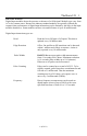
Introduction 1 Available I/O functionality: Analog Input Functions Input value Determines signal levels, with 12 bits resolution Offsets Input values can be software offset, with 12 bits resolution, over the module’s specified range. Gain/ Slope The amplitude of input values can be software multiplied by factors ranging from 0.25 to 4.0. Range Limits The occurrence of input values falling out of user defined upper or lower limits can be flagged.
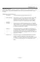
Introduction 1 Digital inputs Read Read the on or off of all inputs Pulse widths The duration of a single or total on/off time of consecutive pulses can be resolved to the nearest 0.00 seconds for a max total of 10.9 minutes, or 46.6 hours with multiplied resolution. Positive or negative edges initiate measurements. The time scale can be multiplied by a factor of 1-256 on a system wide basis. Pulse counting Pulses can be counted up to a total or 65,535.
Introduction 1 Squarewave Can generate squarewaves with programmable On and Off periods. On and Off periods have a base range from 0.01 to 2.56 seconds. Resolution can be further multiplied by a factor of 1-256 on a system wide basis. Re-triggering is available. Pulse Generator Can generate 1-65,535, 50% duty cycle pulses whose equal on and off periods can range from 0.01 to 2.55 Sec. Resolution can be further multiplied by a factor of 1-256 On a system wide basis.
Introduction 1 Specifications Network Communications: duTec supports two standards for transmitting serialized I/O data between the host computer and the BASIC I/O ADs at baud rates to 38,400. Maximum Distance Serial Link Feet Meters RS-422 /485 5,000 1,524 Physical Characteristics: Power Supply 5Vdc@<5A Environment Temperature 0-60 C Humidity 95% Non-Condensing /L Local Control Function (LCF) Options Ordering Information Specify duTec products by model number, e.g.
Introduction 1 Available I/O Modules ANALOG INPUTS, 12 BIT ANALOG OUTPUTS, 12 BIT Voltage OV1 Output 0-1V, self-sourcing OV5 Output 0-5V, self-sourcing OV10 Output 0-10V, self-sourcing Current OI420 Output 4-20mA, self-sourcing To 275 Ohm load Frequency I F10K-B IF2.5K-L IF5K-l IF10K-L Voltage Input 300Hz-10KHz Input 0-2.
Installation 2 Installation Mounting: BASIC I/O ADs come in 4, 8, and 16 channel versions. Figure 2-1 below shows the footprint of each Basic I/OAD. Using corner holes, the unit can be mounted with 4- #6 or #8 round head or pan head screws. The BIO16 version has two additional mounting holes located near the center of the board as well. Hole locations in relation to the overall dimensions for each are shown below. Figure 2-1 BASIC I/O AD Footprint 2-1(Vol.
Installation 2 Power Wiring: Power connections are made at the 2 position terminal block located on the module board marked +5V and GND No. 8 captive wire clamps accept 10-16 AWG wire or spade lugs. Power wiring conventions: + of the power source to the terminal marked +5V - of the power source to the terminal marked GND Power requirements Voltage: 5.0- 5.4Vdc Current: 250 mA + 25mA per digital module and 200mA per analog module.
Installation 2 Designing the Network In order for the BASIC I/O AD to share its data with the host computer, it must be linked via a serial connection. This link can be hard-wired using an RS-422 dual twisted pair or an RS485 single twisted pair connection where the wire run between devices is less than 5000 feet. In any event, the appropriate transmitter of the BASIC I/O AD will be connected to a suitable receiver of the host computer.
Installation 2 RS-422: Advantages: Easier to implement in software since host driver need not be controlled. Can be either Multidrop or Repeat. No turn-around delay required. Disadvantages: Requires five conductor wire instead of three. RS-485: Advantages: Needs only 3 wire conductor. Disadvantages: Host 485 driver control must be implemented requiring tricky serial port manipulations. Can only be Multidrop. Usually requires turn around delay implementation. 2-4(Vol.
Installation 2 RS-485 Programming: The BASIC I/O AD will work equally well when connected as RS-422 or RS-485. However special host programming considerations may be necessary when implementing an RS-485 network. Unlike RS-422 where both the transmit and Receive signals have their own differential pair of conductors, RS-485 utilizes only one differential pair. The single pair of conductors is used bidirectionally and handles both transmit and receive signals.
Installation 2 This interaction is heavily dependant on asynchronous timing. Usually, the Host software has no real means of determining that the instruction has been completely sent. This means that the program must calculate the approximate time necessary to transmit the entire instruction before the RS-485 driver is disabled. Since the BASIC I/O AD can respond very quickly to the instruction, the Host must disable the driver as soon as possible in order to receive the BASIC I/O ADs response.
Installation 2 Network load V.S. Noise suppression: In order to improve RS-485 Bus noise immunity, particularly under tri-state conditions, a pair of “Network Bias Resistors” have been installed in each BASIC I/O AD unit. This design feature has been implemented in order to satisfy the majority of our customers.
Installation 2 Network Type Switches Based upon the selected network configuration, each BASIC I/O AD must be setup before communications can begin. This is done with the network switches shown in figure 2-3. Figure 2-3 BASIC I/O AD Connectors, Switches and Indicators. 2-8(Vol.
Installation 2 The three basic communication connections for individual BASIC I/O ADs are: Repeat Used in RS-422 networks to extend range to 5000 feet between units. Sequential Display reads L1 Multidrop Used in RS-422 or RS-485 networks. Provides a total network range of 5000 feet. Display reads L2 Last Unit Must be used in RS-422 and RS-485 networks for the unit most distant from the host. Sequential display reads L3 If there is only one BASIC I/O AD in a network it is designated L3.
Installation 2 Communications Wiring Host to BASIC I/O AD-RS-422: Figure 2-7 RS-422 Host to BASIC I/O AD Figure 2-7 shows two individually shielded twisted pairs of AWG 24. Each pair has a ground wire connected to its shield. These drain wires are then connected to the signal grounds at each unit. A Separate shield encases the entire cable. The drain wire for this over-all shield is tied to earth ground at one location. An example of acceptable wire for this application would be Belden 8162.
Installation 2 RS-485 Host to BASIC I/O AD: Figure 2-8 RS-485 To-BASIC I/O AD Figure 2-8 shows two individually shielded twisted pairs of AWG24. Each pair has a drain wire connected to its shield. These drain wires are then connected to the signal grounds at each unit. A separate shield encases the entire cable. The drain wire for the over-all shield is tied to earth ground at one end. An example of acceptable wire for this application would be Belden 8162.
Installation 2 BASIC I/O AD TO BASIC I/O AD RS-422 Figure 2-6 RS-422 BASIC I/O AD-To-BASIC I/O AD Figure 2-6 shows one individually shielded twisted pair of AWG 24. Each pair has a drain wire connected to its shield. These drain wires are then connected to the signal grounds at each unit. A separate shield encases the entire cable. The drain wire for the over-all shield is tied to earth ground at one end. An example of acceptable wire for this application would be Belden 8162.
Installation 2 BASIC I/O AD to BASIC I/O AD RS-485 Figure 2-8 RS-485 BASIC I/O AD to BASIC I/O AD Figure 2.8 shows one individually shielded twisted pair of AWG 24. Each pair has a ground wire connected to its shield. These drain wires are then connected to the signal grounds at each unit. A Separate shield encases the entire cable. The drain wire for this over-all shield is tied to earth ground at one location. An example of acceptable wire for this application would be Belden 8162.
Installation 2 Installing the I/O modules: Certain guidelines must be followed when installing I/O modules on the BASIC I/O AD Chassis. In particular the analog modules must be grouped separately from the digital modules on each I/O chassis. Using the worksheets found on the next page, place the desired I/O modules in the indicated positions.
Installation 2 Module Wiring Analog Inputs: Modules should NEVER Be installed or removed while power is applied to the BASIC I/O AD. Following insertion in their respective sockets, modules should be secured with the captive screw. Note: Analog Modules Normally Run hot to the touch Correct polarity connections are essential to proper operation of all the analog inputs. Connections to terminals marked with a + must be more positive than the terminals marked with a -.
Installation 2 Figure 2-12 Analog Voltage, frequency and Current input Wiring Figure 2-13 Temperature Input Wiring 2-16(Vol.
Installation 2 Analog outputs: Modules should NEVER be installed or removed while power is applied to the BASIC I/O AD. Note: Analog modules run hot to the touch. Both voltage and current output modules provide their own isolated power output. This eliminates the need for external power supplies and insures electrical isolation between each output. This also makes it possible to wire voltage outputs in series to obtain larger voltage swings.
Installation 2 Digital Inputs: Modules should never be installed while power is applied to the BASIC I/O AD. With the exception of IDC5S digital input modules, input sensing current fomes from a source external to the BASIC I/O AD. IDC5S input modules provide their own current for sensing contact closures. They can be DESTROYED if an external source is used. The IDC5 and IDC5D input modules are polarity sensitive and operate only when the + terminal is more positive with respect to the - terminal.
Installation 2 Digital Outputs: Modules should NEVER be installed or removed while power is applied to the BASIC I/O AD. The power for ODC5, ODC5A, OAC5, and OAC5A digital output modules comes from a source external to the BASIC I/O AD. Because they contain a protective reverse diode, the ODC5 and ODC5A output modules are polarity sensitive and operate correctly only when the + terminal is positive with respect to the - terminal.
Setup 3 Chassis Setup Figure 3-17 Connectors, Switches, and Indicators During the setup phase of a BASIC I/O AD system, the chassis is given specific values for unit address, analog/ digital separator, network baud rate, and protocol pass type. A momentary pushbutton and seven segment display provide access to these parameters. Figure 3-17 shows the location of these components labeled setup pushbutton and sequential display.
Setup 3 Function Abbrev. Function Address Sequential Display Master Unit Control MC 00h (0) UO=00 Master Unit Digital I/O MD 40h (64) U1=40 Master Unit Analog I/O MA 80h (128) U2=80 The OFFSET addressing mode is more convenient to use as only one address setup is required for each network connection. For example changing the master unit control MC, from 00h to 03h will automatically cause MD=43h; MA=83h.
Setup 3 Baud Rates: Any One of the standard baud rates of 300, 600, 1200, 2400, 4800, 9600, 19200, or 38400 can be used for the serial network communications. The sequential display indicates the letter H followed by the baud rate divided by 100. Basic I/Os are shipped at 9600 baud; the sequential display indicates H096. Changing the BASIC I/O AD baud rate is explained beginning on page 3-4 Protocol Handshake Types: Two protocol handshake types are available, 2 pass and 4 pass.
Setup 3 Changing Setup Parameters Via Pushbutton: During setup the user may need to change the unit address, serial link, baud rate, and protocol pass type. The pushbutton located under the removable cover is used to change these parameters. The pushbuton causes the ajacent red LED to flash each time it is pushed. Any changed values are automatically saved in non-volatile EEPROM.
Setup 3 The display continues to cycle through this sequence until there is a full cycle with no changes. The BASIC I/O AD then stores all values in EEPROM for automatic use following the next power cycle.
Setup 3 Hardware error codes: When the BASIC I/O AD is initially turned on it goes through internal self testing. If anything is not correct, the appropriate error code will flash on the sequential display. Try cycling power, if that does not resolve the error condition please call duTec technical support at 800-248-1632. 3-6(Vol.
Vol.2 Index Analog Inputs . . . . . . . . . . . . . . . . . . . . . . . . . . . . . . . . . . . . . . . . . . . . . . . . . . . . . 1 - 8, 2 - 15 Analog outputs . . . . . . . . . . . . . . . . . . . . . . . . . . . . . . . . . . . . . . . . . . . . . . . . . . . . 1 - 8, 2 - 17 Baud rate . . . . . . . . . . . . . . . . . . . . . . . . . . . . . . . . . . . . . . . . . . . . . . . . . . . . . . . . . . . . . . 3 - 3 Cabling costs . . . . . . . . . . . . . . . . . . . . . . . . . . . . . . . . . . . . . . .
Vol.