DO NOT attempt to operate this machine until you have read and understand ALL safety precautions and operating instructions. Equipment and chemicals when used improperly can be dangerous. H.E.R.O.
H.E.R.O. WARRANTY H.E.R.O. INDUSTRIES, guarantees this airless pump to be free of defects in materials and workmanship to the original owner, for a period of one full year from the date of purchase. The warranty entitles the owner to parts replacement at no charge. The parts replacement warranty is valid for any necessary replacement, whither caused by material or workmanship defect or simple wear. H.E.R.O.
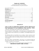
TABLE OF CONTENTS For greatest user satisfaction, please familiarize yourself with all maintenance and operational instructions Important Safety Precautions ..............................................................................................3-4 Introduction...........................................................................................................................5 Operating Instructions .................................................................................................
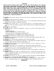
WARNING NEVER PLACE FINGERS NEAR SPRAY TIP OF GUN. NEVER POINT GUN TOWARD ANY PART OF YOUR BODY, OR THAT OF ANY OTHER PERSON. MATERIAL ISSUING FROM THE SPRAY TIP IS AT HIGH PRESSURE. IF FINGERS, OR ANY PART OF THE BODY ARE PLACED NEAR THE TIP OF THE SPRAY GUN, IT IS POSSIBLE THAT THE SPRAY COULD BREAK THE SKIN AND INJECT SOME OF THE SPRAY MATERIAL. IF INJURY DOES OCCUR, SEEK THE IMMEDIATE ATTENTION OF A MEDICAL DOCTOR.
þ þ þ þ þ þ þ þ þ þ þ þ þ þ þ þ þ þ þ ALWAYS follow H.E.R.O. recommendations for operation and safety completely. ALWAYS ensure that switch is in off position before plugging in the electric motor. ALWAYS set trigger lock on gun in "LOCKED" position when not in use, with gun locked close. ALWAYS check connections and fittings for tightness before operating the unit. ALWAYS locate the unit in a well ventilated area a minimum of 25 feet from the spray area.
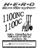
Welcome to the world of H.E.R.O. airless paint spraying. We are sure you will enjoy owning and operating your new H.E.R.O. model 1100NC. With H.E.R.O. airless spray equipment you will avoid the inconvenience and mess of overspray. You are spraying paint, not air, and the paint is driven to the painting surface in a clean, fan shaped spray which penetrates all cracks and corners. To attain these results, you must adjust the pressure as low as possible. We recommend that you become familiar with your H.E.R.O.
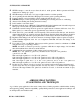
2. 3. Remove shipping seal from under hydraulic tank cap. Re-position paint tank lid knob from the shipping position, on the underside of lid, and place on the lid top. 4. Attach paint hose to outgo tee (ref # 43) and gun to paint hose. NOTE; Spray tip and tip guard should be attached to gun prior to attaching to hose. 5. To assist in clean up, use and install paint tank plastic liners ( accessory item 5 GAL PL ).
relieve pressure. Then set the safety lock on gun to "locked" position with the gun locked closed and immerse the gun in a container of the correct thinner for the paint you are spraying. If shutting down at job completion, for the night, or to change colors; 1. 2. Turn pressure control knob counter clockwise to low pressure setting. Switch unit “OFF”. Remove spray tip from gun and trigger gun back into paint tank. Direct against side of tank. 3. Remove and discard strainer bag. 4.
SYSTEM, EVEN OVERNIGHT. ý NEVER attempt to start the motor when the unit is under pressure. Relieve pressure and follow instructions in "Setting up to spray" ý NEVER attempt to run the motor on longer or lighter extension cord than specified. ý Avoid operating the unit while tilted. Keeping it level assures greater operating efficiency. þ If motor's thermal overload switch has opened, unplug unit and allow it to cool.
The key to all good applications is a good spray gun technique. The finished results are what the client will look at and base his opinion on. Your skill and abilities are as important as good equipment and good paint. Proper application techniques can easily be learned by using the following simple guidelines. If you are not familiar with the basic spray techniques we recommend that you study this portion of the manual and practice the techniques shown.
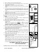
.018 .015 Interior Latex, Exterior Latex, Shake Paint, Exterior Flat Paints. ( 46 OZ. ) Alkyd Flat Enamel, Interior Latex, Semi-Gloss Enamel, Stains. ( 30 OZ. ) FIG. Poor Good Tailing FIG. Good Pattern Fog, Overspray FIG. FIG. FIG. FIG. H.E.R.O.
.013 .011 .009 Fine ground Gloss Enamels, and good quality Stains. ( 23 OZ. ) Clear Varnishes and Lacquers. ( 15 OZ. ) Clear Varnishes and Lacquers. ( 10 OZ. ) NOT: The above volumes achieved with gun wide open for 1 minute and pump spraying at 2000psi. All volumes are approximate. To test worn tips, spray water through the tip at 2000 psi. for 1 minute. Spray into bucket and weigh amount (less weight of bucket).
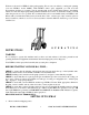
pump is known as the paint or material pump. The paint system is made up of two basic valves, the paint intake valve assembly (ref# 16-28), paint outgo valve, (ref# 32). For correct operation, all four valves must be in good working condition. For this manual we will refer to the two systems as "hydraulic" and "paint". At the center of these two pumps is the diaphragm.
movement causes a vacuum in the paint pump. This vacuum causes the intake valve to open, allowing a new supply of paint to enter. The corresponding paint outgo valve is drawn closed by the vacuum created by the diaphragm. These operations are repeated at a rate of 750 times a minute. These continuously repeated actions draw paint into the pump, pressurize it, and then deliver it to the gun. The failure, of any one valve, to operate correctly will effect the overall equipment performance.
1. 2. 3. 4. 5. 6. 7. 8. Circuit breaker open or fuse blown . Motor not plugged in. Motor not switched on. Motor thermal reset popped. Too light or too long of an extension cord. Pressure control knob loose or missing. Spray tip plugged. Spray tip worn out. 9. Gun handle filter plugged. 10. Paint hose plugged. 11. Loose fitting or hole in siphon hose. 12. Intake siphon hose plugged. 13. Siphon screen missing or plugged. 14. Sprayer under pressure when restarting. 15. Strainer bag plugging siphon screen.
"Diaphragm Test" The solution to almost all problems can be found in the paint side valves, due to the increased wear from contact with the abrasive paint/spray materials. Intake valve (ref# 16-23) and Outgo valve (ref#32) make up the paint valves. Refer to pages where exploded views of these valves are shown. To eliminate the hydraulic side of the pump (piston / oil side of diaphragm) as a source of problems; 1. 2. 3. 4. 5.
2. 3. 4. Pump under pressure. (reduce pressure setting by turning pressure control knob counter-clockwise, trigger gun to relieve pressure). Too light or too long of extension cord. (replace with correct cord. If distance greater than 100 feet, obtain and install extra length of H.E.R.O. airless spray hose). Unit's thermal overload switch has opened. (determine and correct cause of overheating). ELECTRIC MOTOR STALLS/QUITS 1. See "Electric Motor Won't Start/Run 2. Drive belt is loose.
recommendations). 2. Intake ball (ref# 18) worn or jammed opened/closed. (remove intake endcap (ref# 16) and cage (ref# 19). Inspect intake ball, (ref# 18), to ensure it is free, round, and has no nicks or cuts. Inspect for f o r e i g n material jamming ball. Replace parts as needed). 3. Intake seat loose/bypassing. ( run unit under pressure for about ten (10) minutes. Feel endcap for signs of heat. Any signs of heat indicate a fault with the seal between the seat and endcap block.
instructions on page 23-34). CORRECT STATIC PRESSURE, BUT REDUCED SPRAYING PRESSURE (Check with pressure gauge, see page 15 for details). 1. Spray tip worn out/too large. (replace with new, correct sized spray tip. Tip most not exceed a newer condition .026 tip ). 2. Paint hose incorrect. (replace hose with genuine H.E.R.O. airless spray hose (min. 50 feet). Steel braided hoses must not be used ). 3. Intake valve seat (ref# 17) worn. (replace intake seat closely following detailed instructions on page 21).
3. Too short a length of hose. (minimum 50' of airless spray hose is required. Replace or add hose until a minimum of 50' is being used). FLUID BEING SPRAYED OUT OF TIP PULSATES, SPRAY HOSE CONTINUES TO MOVE VIGOROUSLY WHEN GUN TRIGGER CLOSED 1. Outgo valve (ref# 32) assembled incorrectly. (remove the outgo valve and reassemble closely following the instructions on page 22). 2. Outgo valve ball (ref# 36) worn out or jammed. (inspect outgo ball to ensure that it is round and free of nicks or cuts.
-1/2" Open end wrench (2) -4-45-3 (accessory item) -Torque wrench Removal ] 1. Tilt unit up nose. 2 . Small Steel Plate ] ] ] ] ] - Items contained in 4-22CRK on it’s Remove the Large Steel e i g ht bolts Plate securing the material head (ref# 23) to the hydraulic head (ref# 51). 3. Remove diaphragm and examine large steel plate ( front ) of the diaphragm assembly. Replace entire assembly if sharp edges are evident. 4. Dismantle old diaphragm. 5.
This area must be spotless before the new seat is installed. 1 . A 2. 3. 4. 5. 6. 7. 8. 9. 10. 11. 12. 13. 14. 15. 16. Remove the four bolts (ref# 14) and pull intake endcap (ref# 16), from the pump. Remove the intake elbow (ref# 13), cage (ref# 19) and ball (ref# 18) from the endcap. Use a socket or screw driver and hammer to tap to press the seat out of the endcap block. Access from the side where the elbow was removed. Inspect the machined area “A” from which the seat was removed.
OUTGO VALVE (REF# 34) TOOLS REQUIRED -1" wrench -vise -Teflon tape 1. 2. 3. 4. 5. 6. 7. 8. 9. 10. 11. 12. 13. 14. 15. Remove pressure control knob, (ref# 71) and pull P.C. stem, (ref# 74) out to internal stop, thereby releasing hydraulic pressure. Trigger gun to release pressure from the material side of pump. Disconnect outgo tee assembly, (ref# 43) from outgo swivel, (ref# 40) on the outgo valve. Remove outgo valve from machine by turning counter clockwise.
(REF# 86) A B TOOLS REQUIRED -1/2" wrench -11/16" wrench -circlip pliers -torque wrench -grease -vise grips 90 89 C 88 87 1. Remove hydraulic feed line, (ref# 60) from hydraulic intake valve, (ref# 59) and also remove hydraulic return line, (ref# 69) from the pressure control valve, (ref# 70). Plug lines to minimize oil loss. (Hint; golf tees work well for this) 2. Remove the bolts, (ref# 57) passing through the side frames, (ref# 106, 107), into the crossblock, (ref# 56). 3.
13. 14. 15. 16. 17. 18. 19. 20. 21. 22. 23. 24. 25. internal circlip groove of piston using circlip pliers. NOTE: Circlip must fully expand into groove of piston. Circlip has fully expanded when there is 13/64" space between circlip eyelets. NOTE: If you experience difficulty installing circlip, remove a small quantity of grease. When installed correctly, rod should move slowly and without any free play.
7 8 7 7 7 7 T O O L S 7 7 7 8 8 8 8 8 REQUIRED -1" wrench -11/16" wrench 1. Remove pressure control knob, (ref# 71) and pull P.C. stem, (ref# 74) out to the internal stop (1/16" to 1/8") thereby releasing hydraulic pressure. 2. Remove hydraulic return line, (ref# 69) from P.C. fitting, (ref# 78). 3. Place 11/16" wrench on P.C. seat, (ref# 83). Turn counter-clockwise to remove complete valve. 4. Place complete valve in vise and remove seat from body, (ref# 79). 5.
114 115 117 3-WHIPEND 620-H2O 67/18B 10-55-011-2 10-55-011-4 10-55-013-2 10-55-013-4 5GAL SB 5GAL PL 10-55-____ 4-649 4-655 4-660 4-662 4-664 661 4-666 4-668 444-6654 4-6655 4-LVO-1 4-LV0-4 4-67/19 4-45-3 10-QRP-3 10-QRP-5 10-QRP-8 HOSE, AIRLESS PAINT 50' X 1/4" HOSE, AIRLESS PAINT 25' X 1/4" HOSE, AIRLESS PAINT 50' X 3/8" WHIPEND, 3' X 3/8" HOW TO OPERATE VIDEO TAPE, VHS FORMAT HEX KEY SET, 5/16",1/4",5/32",1/8" AIRLESS SPRAY GUN, ASM 400, 2 FINGER TRIGGER, WITH 1710 ZIP TIP AIRLESS SPRAY GUN, ASM 400, 4
PARTS LIST Please order parts by the appropriate part number and not by reference number. The quantity required, per unit, is shown for each part number. Part numbers in bold text indicate whole assemblies or kits.
PARTS LIST Please order parts by the appropriate part number and not by reference number. The quantity required, per unit, is shown for each part number. Part numbers in bold text indicate whole assemblies or kits.
PARTS LIST Please order parts by the appropriate part number and not by reference number. The quantity required, per unit, is shown for each part number. Part numbers in bold text indicate whole assemblies or kits.
PARTS LIST Please order parts by the appropriate part number and not by reference number. The quantity required, per unit, is shown for each part number. Part numbers in bold text indicate whole assemblies or kits.
PARTS LIST Please order parts by the appropriate part number and not by reference number. The quantity required, per unit, is shown for each part number. Part numbers in bold text indicate whole assemblies or kits.
1100MD SCHEMATIC 2 1 140 139 12 7 4 12 147 5 8 9 10 134 12 135 7 12 133 11 143 146 130 129 145 115 13 118 14 123 124 58 13 13 57 116 H.E.R.O.
PARTS SCHEMATICS H.E.R.O.
AUTHORIZED SALES AND SERVICE CENTERS- U.S.A. Call H.E.R.O.’s Toll Free Helpline 1-800-464-HERO (4376) or take your unit to your nearest authorized H.E.R.O. dealer. Help is available to answer all your sales and service questions, weekdays from; 7:00 AM-4:30 PM ( Pacific Time ). After hours calls are recorded and returned the next business day. þ Full Parts and Service ý Parts Only Sales North West: North Central: North East: Bentley Co. Inc.
AUTHORIZED SALES AND SERVICE CENTERS- U.S.A. SOUTHERN CALIFORNIA Bakersfield Paint, 401 Sumner Street, Bakersfield, CA 93305 805-327-8431 Diefel’s Paint, 1030 Alta Vista, Bakersfield, CA 93305 805-325-7201 Sequoia Paint Company, 700 Baker, Bakersfield, CA 93305 805-323-7948 State Paint Comp any Inc., ý 3920 W. Magnolia, Burbank, CA 91505 818-845-3745 Decratrend Paint, 68 - 845 Perez Road, Cathedral City, CA 92234 619-324-4615 A-1 Equipment Sales, 19034 E.
AUTHORIZED SALES AND SERVICE CENTERS- U.S.A. Boise, ID 83705 208-336-7210 Ponderosa Paint, All Pro, 4631 Aeronca Street, Boise, ID 83705 208-376-4431 Broadway Paint & Glass, 1305 Broadway, Boise, ID 83706 208-345-1581 State Paint & Glass, 4774 W. State Street, Boise, ID 83703 208-336-7210 Caldwell Paint & Glass, 916 Cleveland Blvd., Caldwell, ID 83605 208-459-0838 Nampa Paint & Glass, 816 - 3rd. Street S., Nampa, ID 83651 208-466-3547 ILLINOIS Spray Systems Specialists, 172 W.
AUTHORIZED SALES AND SERVICE CENTERS- U.S.A. Denfeld Paint, 1851 N.E. 2nd Street, Bend, OR 97701 503-382-4171 Miller Paint Company, 2811 N.W. Grant, Corvallis, OR 97330 503-758-4458 J’s Color Center, 1986 W. 6th Avenue, Eugene, OR 97402 503-345-2397 Tommy’s Paint Pot, 1745 W. 11th Avenue, Eugene, OR 97402 503-683-5851 Jon’s Airless Spray, 8225 N. Applegate Road, Grants Pass, OR 97527 503-862-2680 Miller paint Company, 1831 W. Powell Blvd., Gresham, OR 97080 503-666-9018 SprayFix, 120 S.
MANUFACTURED BY: H.E.R.O. INDUSTRIES 2719 LAKE CITY WAY BURNABY, B.C. CANADA PHONE: FAX: 604-420-6543 800-494-4376 604-420-8725 PURCHASED FROM __________________________ __________________________ __________________________ __________________________ MODEL: __6-1100__ -LA__ SERIAL #: _________________ DATE OF PURCHASE: ________________ H.E.R.O.