GIDM INDUSTRIAL / COMMERCIAL PACKAGED FURNACES INSTALLATION, OPERATION AND MAINTENANCE MANUAL (Suitable for Operation with up to 100% Fresh Air) READ MANUAL CAREFULY BEFORE INSTALLING OR OPERATING THE FURNACE FOR YOUR SAFETY If you smell gas follow these instructions, 1) Open windows. 2) Do not touch electrical switches. 3) Extinguish any open flame. 4) Call the gas supplier immediately.
RECEIVING AND WAREHOUSING Inspect the unit upon arrival for any shipping damage. If any part is missing or damaged, notify the carrier at once. If the unit cannot be installed immediately, store it and its accessories in a clean and dry place. HANDLING AND SUSPENSION Do not handle the unit by attaching hooks, jacks or chains to the unit casing or any other component. Spreader bars are recommended when making single point lifts.
For service, it is advisable to maintain a minimum 24-inch clearance on the side opposite the controls and 42-inch clearance on the control side. If this unit is to be operated within a confined space or within a building of unusually tight construction, air for combustion and ventilation must be obtained from outdoors or other spaces freely communicating with the outdoors.
1) FOR POWER VENTED UNITS: The flue draft should be adjusted at the damper of the induced draft fan when the unit is operating on high fire. The overfire draft measured with a manometer at the test port in the relief door should be minus 0.01 to minus 0.50 in W.C. as specified on the rating plate of the unit. 2) FOR GRAVITY VENTED UNITS: The flue draft should be adjusted at the damper of the burner fan when the unit is operating at high fire.
*A tee shall be installed in the supply line at the same elevation as the gas inlet connection. The tee must be equipped with a nipple and pipe cap to serve as a condensate collector. *Test for tightness of gas connections after installation. GAS VENT High gas pressure regulator (if required), low pressure regulator, pilot pressure regulator, gas pressure switch (if supplied), and normally open vent valve (if supplied) must be vented outside of building for an indoor unit.
5. Lubricate (if necessary) the burner, induced draft fan and main fan motors. The specifications on the motors for grease and oil shall be adhered to. 6. Check heater outlets and exhauster, or induced draft discharge for obstructions. 7. Check fan-limit control.
5. Check supply fan motor load against rating plate figure. If actual figure is significantly different than the rating plate value, take corrective actions with respect to duct work and accessories external to the unit 6. The thermal overloads must be left set appropriate to the motor performance after all adjustments have been made. 7. Repeat steps 2 through 6 for the induced draft fan motor (power vented units only). 8. Remove jumper from fan switch if installed in step 4 above. 9.
The equipment has been electrically and fire tested prior to shipment. However, during transit, misadjustment of controls and loose wires could develop. Do not assume a control is defective until it and its associated wiring is checked. This equipment has may items supplied to us by outside vendors. This manual is accompanied by information sheets on most of these items which should be referred to for detailed service information.
6. UNABLE TO ADJUST FIRE TO BURN CLEANLY. A) B) C) D) E) 7. Insufficient exhauster* draft. Insufficient or too much fuel at supply. Incorrect adjustment of air shutters at burner. Insufficient combustion air available. Burner blower wheel running backwards. INSUFFICIENT HEAT BEING DISCHARGED INTO AREA. A) B) C) D) E) Main fan blowers running backwards. High limit switch setting too low or defective. Burner locked in low fire position. Ductstat setting improper or defective.
NOTE: Refer to manufacturer literature provided for maintenance requirements of optional equipment. BEARING INSTALLATION AND MAINTENANCE NOTE: To prevent premature failure – please ensure greasing instructions below are applied. As well, tighten bearing set screws, collars, and wheel lugs every four to six months.
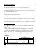
Table 1. Recommended Lubrication Ball Bearings Shaft Size (inches) 1/4 to 3/16 1/2 to 3/4 1-1/4 to 1-1/2 1-11/16 to 1-15/16 2 to 2-7/16 2-1/2 to 2-15/16 3 to 3-7/16 3-1/2 to 4 - Roller Bearings Grease Charge (ounces) 0.03 0.1 0.15 0.2 0.3 0.5 0.85 1.5 - Shaft Size (inches) 1-3/16 to 1-1/4 1-3/8 to 1-7/16 1-1/2 to 1-11/16 1-3/4 to 2 2 to 2-3/16 2-1/4 to 2-1/2 2-11/16 to 3 3-3/16 to 3-1/2 3-15/16 to 4 4-7/16 to 4-1/2 Grease Charge (ounces) 0.1 0.22 0.32 0.5 0.55 0.65 0.85 1.25 2.5 3.
TENSIONING V-BELT DRIVES 1. 2. 3. 4. 5. Ideal tension is the lowest tension at which the belt will not slip under peak load conditions. Check tension frequently during the first 24-48 hours of operation. Over-tensioning shortens the belt and bearing life. Keep belts free from foreign material that may cause slip. Make V-drive inspection on a periodic basis. Tension when slipping. Never apply belt dressing as this will damage the belt and cause early failure. Check and tighten belt tension.
GIDM INDUSTRIAL HEATER - WARRANTY I.C.E. MFG. LTD. WARRANTS THAT IT WILL SUPPLY TO OR REPAIR FOR THE PURCHASER OF THIS PACKAGE UNIT HEATER THE HEAT EXCHANGER FREE OF CHARGE F.O.B. FACTORY IF SAID HEAT EXCHANGER WEARS OUT OR FAILS UNDER NORMAL USE AND SERVICE DUE TO A DEFECT IN MATERIAL AND/OR WORKMANSHIP DURING FIVE (5) YEARS FROM DATE OF SHIPMENT FROM THE FACTORY PROVIDED AN ALL STAINLESS HEAT EXCHANGER IS PROVIDED.
ECONOMITE 400-33 & F400-33 GAS BURNERS INITIAL START UP AND ADJUSTMENT CAUTION: Only qualified service personnel should attempt initial start-up. 1. Study these instructions, the wiring diagrams and flame safeguard instructions. Locate and identify all of the burner components. 2. Have on hand: CO and CO2 tester, stack thermometer, 0” to 30” W.C. gas pressure gauge, U-Tube manometer and DC volt meter. 3. Make the proper setting on all limit controls and set the operating control to call for heat. 4.
22. Make the final setting of the air shutter by checking the flue gases with an “Orsat” or other similar combustion testing instrument. There should be no carbon monoxide and the carbon dioxide content should be within limits prescribed by the local gas company. Make sure that the main air shutter is locked securely in place. 23. Recheck pilot to make sure that its operation has not deteriorated because of main shutter adjustment. If necessary, readjust pressure regulator. 24.
ECONOMITE 400-33 & F400-33 GAS BURNERS PART # DESCRPTION 3981-001 4” Diameter Stainless Sleeve PART # 5253-01 4904-45 Quadrant-Air Shutter Adjustment 5253-10 DESCRIPTION Pilot assembly with insulators, rods, temflex and baffle. PVC tubing—7/16”I.D. x 2” long 4905-15 Air shutter-Internal 5234-40 Flame rod Gland Nut 4917-00 Main Orifice Holder 5234-50 Flame rod assembly. 4918-11 Orifice Elbow (1” NPT) 5249-01 Pilot air baffle.
GP TYPE C FORCED DRAFT BURNER C-6.2 TO C-12.9 INITIAL START UP 1. Make sure burner power switch is off and manual main and pilot valves are closed. 2. Make proper settings on limit controls. 3. Have on hand CO and CO2 tester, stock thermometer, 0” to 30”W.C. gas pressure gauge, u- tube manometer and D.C. volt meter. 4. Turn on burner power switch momentarily to check blower rotation. 5.
BURNER SAFETY CHECK 1. Start and stop burner several times to ensure proper operation. 2. Check operation of combustion safeguard control by simulating a flame failure, making certain the burner locks out on safety within the proper time. 3. Check operation of the air flow switch, making certain fuel valve closes when the air flow diaphragm switch opens. 4. Bypass discharge controller and check to ensure high limit will shut down burner on temperature increase. If changed reset as per factory setting. 5.
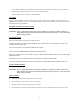
NOTE: Revision Description UNIT MAY NOT BE EXACTLY AS SHOWN. LOUVERED INLET SECTION SOME FIELD WIRING TO BE CONNECTED BETWEEEN SECTIONS BY CONTRACTORS ON UNITS SHIPPED IN SECTIONS TO JOB SITE. Rev By BLOWER/FILTER SECTION WEATHERHOUSING SECTION Date HEATING SECTION NOTE: DRAWN BY DEC. 18/98 DATE ISSUED BY CHK. BY JV JS DRW. NO. COIL SECTION SCALE FIG I JOB NO.
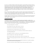
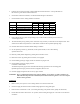
RAIN CAP E EXHAUST STACK 14 GA. NON-CORROSIVE STEEL WEATHER SKIRT 36" MIN. ABOVE HIGHEST POINT ON BUILDING MODEL STACK SIZE A B C D E 25-75 8"Ø 8 12 18 30 5 85-100 10"Ø 10 14 20 32 5 125-175 12"Ø 12 16 22 34 6 200-250 14"Ø 14 20 24 36 8 275-400 16"Ø 16 24 28 38 10 500-600 18"Ø 18 26 32 42 12 ROOF ROOF FRAMING STACK SUPPORT NOTES: 1. REFER TO ENGINEERING RATING FOR MINIMUM RECOMMENDED STACK SIZES. (FORM GIDM-S100) FOR POWER VENTERS.
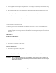
BURNER MOTOR 1. THE ABOVE SETTING IS IN LOW FIRE POSITION. LONG CRANK ARM ON BURNER 2. THE PRIMARY AIR ON BURNER TO BE ONLY 1/2-1 TURN OPEN AT SET SCREW. PRIMARY AIR DAMPER BALL JOINT ABOUT 3/4 DOWN FROM PIN 3. TO DECREASE PRIMARY AIR ON HIGH FIRE MOVE BUTTERFLY CRANK ARM DOWN CLOSER TO HORIZONTAL POSITION. SHORT CRANK ARM BUTTERFLY VALVE ARM LOW & HIGH BUTTERFLY SETTING GIDM GRAVITY VENTED F-400-33 BURNER LINKAGE OPERATION (POWER VENT) 1. INSTALL A MANOMETER ON SUCTION AT TEST PORT IN POP-UP DOOR.
A91, T91 THERMISTOR SENSOR PROPORTIONAL BAND R B THE PROPORTIONAL BAND ADJUSTMENT, LOCATED ON THE TERMINAL BOARD, IS ADJUSTABLE BETWEEN 2 AND 30°F (1.1 TO 16.7FC). FIELD ADJUSTMENTS ARE MADE WITH THE SYSTEM IN OPERATION. TURN THE PROPORTIONAL BAND ADJUSTMENT UNTIL THE SYSTEM STABILIZES AND THE MOTOR ACTUATOR NO LONGER OSCILLATES. M100 WITH R81Q S2 P B S1 IN C T2 SET POINT I N C TR 24 V.A.C.
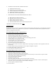
POSITION OF THE IGNITION ELECTRODE FOR STRAIGHT GAS BURNERS, USING A FLAT DIFFUSER PLATE. 1/4" 3 5/8" 1/16" - 1/8" IGNITION ELECTRODE: THE IGNITION ELECTRODE IS POSITIONED AS SHOWN, WITH THE HORIZONTAL PART OF THE ELECTRODE FLUSH WITH THE DIFFUSER PLATE, LEAVING A GAP OF 1/16" TO 1/8" WIDE. THE POINTING DIRECTION OF THE ELECTRODE IS AS SHOWN, BUT IS NOT CRITICAL. FLAME SENSOR: THE FLAME SENSOR SHOWN IS A RECTIFICATION- OR FLAME ROD. A UV SCANNER CAN BE USED INSTEAD.
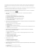
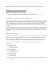
Rev By 1 2 3 4 Revision Description 5 11 16 6 Date 9 15 12 10 8 7 13 GIDM SERIES 14 TITLE 15 14 13 12 11 10 9 8 7 6 5 4 3 2 1 AIR PROVING SWITCH ELECTRICAL BOX MOTOR MOTOR MOUNTING PLATE BLOWER WHEEL MESH SHIELD AND INLET ORAFICE IGNITION TRANSFORMER PILOT, IGNITOR AND SENSOR ASSEMBLY FIRING TUBE GAS LINE IN/ORIFACE LOCATION FAN BOX PILOT REGULATOR & SOLENOID PILOT SHUT OFF VALVE DAMPER CONTROL REAR COVER PLAT SIGHT GLASS & SEAL SCALE FIG VII DRW. NO.
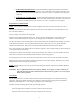
SLEEPER CURB SIDES BASE FRAME FLASHING (BY OTHERS) ROOFING PAPER (BY OTHERS) CURB ENDS CENTER CURB BRACING DUCT SUPPORT ANGLE ONE EXAMPLE OF CURBING UNIT NEOPRENE GASKET OR CAULKING (BY OTHERS) WOODEN NAILER INSULATION (BY OTHERS) CANT STRIP (BY OTHERS) ROOF CURB DETAIL CURB ENDS DUCT COLLAR BY OTHERS LOUVERED INLET SLEEPER DAMPER SLEEPER DETAIL MATERIAL = 16 GA. CB.