
User Manual

GENERAL EM -5
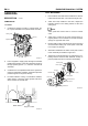
TIMING GEAR
1. Timing gear is installed in the timing gear case at the
frontofengine.
2. Each gear is helical gear manufactured with high pre-
cision and its surface is treated by heat to enhance
the durability.
3. Timing marks are marked on the gear. When assem-
bling, by aligning the timing marks, gears can be en-
gaged correctly.
Camshaft gear
Supply
pump gear
Idler gear A
Crankshaft gear
Idler gear B
SUDEM7012L
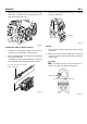
4. Bushes are press-fit into idler gear, which rotates idler
shaft A (1) and idler shaft B (2). Idler shaft and gear oil
hole provides oil passage to lubricate bush and gear.
1
2
SUDEM7013L
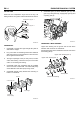
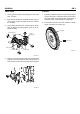
FLYWHEEL
1. Flywheel is made of forged iron. Pilot bearing of trans-
mission drive pinion is disposed at the center portion.
Ring gear which can be geared with starter pinion is
pressed fit at the circumferential of the flywheel.
2. Processed is formed at the outer diameter of the fly-
wheel to measure the engine rpm.
Ring gear
Processed
SUDEM7014L