
User Manual

GENERAL EM -3
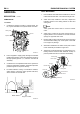
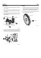
7. Camshaft assembly (1) consists of cam sensor plate,
thrust plate, cam and journal. Camshaft gear is cou-
pled with the idler gear A (2).
2
1
SUDEM7004L
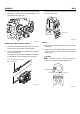
CRANKCASE AND CYLINDER S LE EVE
1. Crankcase is manufactured firmly with cast iron to
prevent stress concentration and deformation.
2. The 5 camshaft bushes are installed to the camshaft
bore of the crankcase.
To facilitate the removal and installation of camshaft,
inner diameter of bush is tapered to the rear side.
Do not remove the cam sensor plate
unless it is damaged.
SUDEM7005L
3. Cylinder sleeve made of special cast iron is pressed
fit into the crankcase.
Cylinder sleeve
Crank case
SUDEM7006L
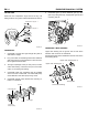
PISTON
1. Piston pin type is full float type and piston pin is offset
from thrust.
2. Marks on the piston indicate weight, part number and
oversize. The front mark indicates the front direction
of the engine.
NOTE
When assembling a piston, let the arrow mar k (→)
faced to the center of cylinder head bolt hole.
Weight mark
Part number
Front mark
SUDEM7007L