
User Manual

EM -2 ENGINE MECHANIC AL SYSTEM
GENERA
L
DESCRIPTION EFA0EBB7
COMBUSTION
CHAMBER
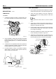
1. Combustion chamber consists of cylinder head, pis-
ton, injector installed to the cylinder head and valve.
Valve guide
Cylinder head
Valve
Piston
Injector
SUD
EM7001L
2. Fuel is supplied to supply pump through the fuel filter
installed to the frame. Fuel is also supplied to injectors
through injection pipe No. 1, 2, 3 and 4 in common rail
assembly.
3. Combustion is accomplished when fuel is injected di-
rectly into combustion chamber, at that time explosion
pressure applies to the piston directly.
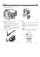
4. Fo
r better efficient cooling of combustion chamber,
wa
ter director is press-fit under cylinder head floor,
wh
ich induces the coolant flow.
Water director
Engine coolant
SUDEM7002L
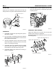
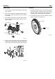
VALVE MECHANISM
1. Heat resistant steel with surface treatment is used for
intake and exhaust valve. The valve seat angle is 45
.
2. Valve stem seal, installed to the stem, adjusts the
lubricant amount on the sliding surface of valve and
valve guide.
NOTE
Valve guide with carbon cutter is used for exhaust
valve.
3. Valve spring consists of two valve springs having ir-
regular pitches. The coil directions of inner and outer
springs are opposite each other.
4. Rocker shaft is hollow cylindrical rod, whose each end
are sealed with sealing cap. Inner space of the shaft
is an engine oil passage.
5. Steel ball is installed to the lower end of push rod and
rocker assembly is installed to upper end.
6. Tappet has a cylindrical shape. As enlarging the con-
tacting surface contacted with camshaft, it helps to
prevent partial wear and to increase its durability.
Outer spring
Inner spring
Rocker
Rocker shaft
Push rod
Tappet
Camshaft
Intake valve
Exhaust valve
Valve guide
Valve spring
SUDEM7003L