ENGINE MECHANICAL SYSTEM (D4DD) GENERAL DESCRIPTION ............................................. SPECIFICATION ......................................... SPECIAL TOOL ........................................... DIAGNOSIS ................................................. ADJUSTMENT ............................................. EM EM EM EM EM -2 -6 -12 -15 -16 EM EM EM EM EM -17 -19 -22 -25 -26 EM EM EM EM EM EM EM -31 -33 -36 -37 -41 -43 -44 TIMING SYSTEM TIMING GEAR ASSEMBLY COMPONENTS ..............
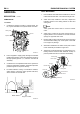
EM -2 ENGINE MECHANICAL SYSTEM GENERAL DESCRIPTION VALVE MECHANISM 1. Heat resistant steel with surface treatment is used for intake and exhaust valve. The valve seat angle is 45 . 2. Valve stem seal, installed to the stem, adjusts the lubricant amount on the sliding surface of valve and valve guide. EFA0EBB7 COMBUSTION CHAMBER 1. Combustion chamber consists of cylinder head, piston, injector installed to the cylinder head and valve. NOTE Valve guide with carbon cutter is used for exhaust valve.
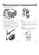
GENERAL 7. EM -3 Camshaft assembly (1) consists of cam sensor plate, thrust plate, cam and journal. Camshaft gear is coupled with the idler gear A (2). 3. Cylinder sleeve made of special cast iron is pressed fit into the crankcase. 2 Crank case Cylinder sleeve 1 SUDEM7006L SUDEM7004L CRANKCASE AND CYLINDER SLEEVE 1. Crankcase is manufactured firmly with cast iron to prevent stress concentration and deformation. 2. The 5 camshaft bushes are installed to the camshaft bore of the crankcase.
EM -4 ENGINE MECHANICAL SYSTEM PISTON RING 6. Piston has two compression rings and one oil ring. All sliding surfaces of rings are coated with hardened chrome. Crankshaft gear (1) drives camshaft gear (2), idler gear A (3), idler gear B (4), supply pump gear (5) and oil pump gear (6). 3 Compression ring No. 1 5 2 Compression ring No. 2 Oil ring No. 3 4 6 1 SUDEM7010L SUDEM7008L CRANKSHAFT 1. Crankshaft is forged with high-strength alloy built in with balance weight. 2.
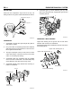
GENERAL EM -5 TIMING GEAR FLYWHEEL 1. Timing gear is installed in the timing gear case at the front of engine. 1. 2. Each gear is helical gear manufactured with high precision and its surface is treated by heat to enhance the durability. Flywheel is made of forged iron. Pilot bearing of transmission drive pinion is disposed at the center portion. Ring gear which can be geared with starter pinion is pressed fit at the circumferential of the flywheel. 2.
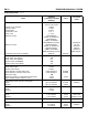
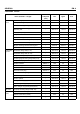
EM -6 SPECIFICATION ENGINE MECHANICAL SYSTEM ECC41378 Items General Type Cylinder inner diameter Cylinder stroke Displacement Compression ratio Firing order Maximum output Maximum torque Compression pressure (at 200rpm) Valve timing Intake valve open (BTDC) Intake valve close (ABDC) Exhaust valve open(BBDC) Exhaust valve close (ATDC) Standard ([ ] indicates standard diameter) Serial 4-cylinder 4stroke common rail system 104mm 115mm 3,907cc 17.
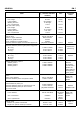
GENERAL EM -7 Items Outer side valve Spring Free height Load installed Winding direction Out of squareness Inner side valve spring Free length Load installed Winding direction Out of squareness Standard ([ ] indicates standard diameter) 66.1mm 26.5~29.3kg To the right 1.5mm 60.0mm 11.5~12.7kg Left side 1.5mm Limit 63mm 23.7kg 57mm 10.3kg 2.1mm 104.00~104.03mm Below 0.07mm 0.07mm 0.05mm [28] 0.045~0.096mm Clearance between piston ring and piston ring groove No.1 ring No.2 ring Oil ring 0.106~0.
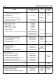
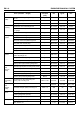
EM -8 ENGINE MECHANICAL SYSTEM Items Connecting rod Connecting rod twist and distortion Oil clearance Connecting rod bearing Free length of connecting rod bearing Bearing crush (measured load 600kg) Connecting rod endplay Camshaft Intake cam max. length Intake cam min. length Intake cam lift Exhaust cam max. length Exhaust cam min.
GENERAL EM -9 TIGHTENING TORQUE Screw size O.D×pitch (mm) Nm kgf.m Ib-ft M14×2.0 49+90 5.0+90 36.4+90 Front plate flange bolt(8 ×16) ― 18.6~27.4 1.9~2.8 13.8~20.4 Rear oil seal slinger flange bolt(6×12) ― 7.8~11.8 0.8~1.2 5.8~8.7 Supply pump side timing gear case mounting bolt ― 18.6~27.4 1.9~2.8 13.8~20.4 Supply pump flange bolt ― 16.7~25.5 1.7~2.6 12.4~18.9 Oil jet check valve M12×1.25 29.4 3.0 21.8 Rear plate flange bolt(10×22) M10×1.5 63.7 6.5 47.
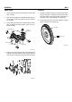
EM -10 ENGINE MECHANICAL SYSTEM Screw size O.D×pitch (mm) Nm kgf.m Ib-ft Fan clutch mounting flange bolt (8) ― 21.6~32.3 2.2~3.3 16~24 Fan clutch spring washer bolt(8×25) ― 16.7~25.5 1.7~2.6 12.4~18.9 Fan flange nut (6) ― 3.9~5.9 0.4~0.6 2.9~3.6 Thermostat cover case flange bolt ― 21.6~32.3 2.2~3.3 16~24 Engine coolant temperature sensor and gauge ― 29.4~39.2 3.0~4.0 21.8~29.1 Thermostat case flange bolt(10×25) ― 35.3~52.9 3.6~5.4 26.2~39.
GENERAL Intake manifold Exhaust manifold Engine cover EM -11 Items (diameter × length) Screw size O.D×pitch (mm) Nm kgf.m Ib-ft Actuator mounting flange bolt ― 7.8~11.8 0.8~1.2 5.8~8.7 Butterfly valve shaft mounting nut (8) ― 16.7~27.4 1.7~2.8 12.4~20.4 Intake manifold front hanger mounting flange bolt (10×20) ― 32.3~49 3.3~5.0 24~36.4 Intake manifold mounting flange bolt (8 ×20) ― 18.6~27.4 1.9~2.8 13.8~20.4 Exhaust manifold heater protector cover mounting bolt M8×1.25 11.
EM -12 SPECIAL TOOL ENGINE MECHANICAL SYSTEM E2E65F7D Tool (part no.
GENERAL Tool (part no.
EM -14 Tool (part no.
GENERAL DIAGNOSIS EM -15 E252285B Possible cause Symptom Compression pressure is excessively low Maintenance Cylinder head Gasket is melt Piston ring is worn or damaged Piston or cylinder is damaged Valve seat worn or damaged Replace gasket (check the status of head surface, block head) Replace the ring Repair or replace piston or cylinder block Repair or replace valve or seat ring Engine oil depleted Oil pressure switch fail Oil filter clogged Oil pump gear or case is worn Engine oil viscosity is lo
EM -16 ENGINE MECHANICAL SYSTEM Possible cause Symptom Maintenance Exhaust gas leaks Connection is loose Pipe or muffler is damaged Retighten Repair or replace Unusual noise Baffle plate inside the muffler fell off Rubber hanger is damaged Pipe or muffler interferes with the body Pipe or muffler is damaged Replace Replace Repair Repair or replace ADJUSTMENT 7. E148032F COMPRESSION PRESSURE 1. 2. Crank the engine and measure the compression pressure.
TIMING SYSTEM EM -17 TIMING SYSTEM TIMING GEAR ASSEMBLY COMPONENTS E2F63E1E 58.8~68.6 (6.0~7.0, 43.6~50.9) 26 25 23 19 17 20 21 22 18 11 16 10 15 18.6~27.4 (1.9~2.8, 13.8~20.4) 9 24 14 3.9~5.9 (0.4~0.6, 2.9~4.4) 12 8 13 7 6 5 4 3 60.0 2 1 Cam sensor plate 20. Thrust plate 21. Idler gear A 22. Idler shaft 23. Oil pump gear 24. Crankshaft gear 25. O-ring 26. Power steering oil pump Tightening Torque : Nm (kgf.
EM -18 ENGINE MECHANICAL SYSTEM If the cam sensor plate is not damaged, do not remove. 2 1 18.6~27.4 (1.9~2.8, 13.8~20.4) 7 8 58.8~78.4 (6.0~8.0, 43.6~58.2) 6 5 4 3 1. 2. 3. 4. 5. 6. 7. 8. Thrust plate Semicircular key No.1 camshaft bush No.2 camshaft bush No.3 camshaft bush No.4 camshaft bush No.5 camshaft bush Sealing cap Tightening Torque : Nm (kgf.
TIMING SYSTEM REMOVAL 1. EM -19 4. E812C03D Remove the vacuum pump (1) and alternator assembly (2). Loosen the alternator (1) tensioner screw (2) and remove the V-belt(3). 2 2 1 SUDEM7021L 1 3 SUDEM7018L 2. 5. Remove the power steering pump (1). Remove the cooling fan (1) and auto cooling fan coupling (2). 1 2 1 SUDEM7022L 6. SUDEM7019L 3. Align the timing mark "0" of crankshaft damper pulley (1) with the indicator (2) of the timing gear case. Then, cylinder No.
EM -20 7. ENGINE MECHANICAL SYSTEM Remove the crankshaft damper pulley nut (2) and remove the crankshaft damper pulley (1). NOTE Check the front oil seal (1) state. If it is normal, do not remove it. 2 1 1 SUDEM7024L 8. Remove the engine coolant temperature sensor (1) connector and remove the thermostat housing (2) from the cylinder head. SUDEM7027L CAUTION Before removing the timing gear case, remove timing gear case mounting bolt (1) at the supply pump first.
TIMING SYSTEM EM -21 10. Remove the front oil seal slinger (1). 13. Remove the idler gear B (1). 1 1 SUDEM7029L 11. Remove the oil pump gear (1). SUDEM7032L 14. Remove the supply pump gear (1). 1 1 SUDEM7030L 12. Remove the idler gear A (1). SUDEM7033L 15. Remove the camshaft assembly. 1. Remove the thrust plate-mounting bolt (4) through cam sensor plate (2) hole (3) of camshaft gear (1).
EM -22 ENGINE MECHANICAL SYSTEM NOTE Do not remove the cam sensor plate (2), if it is not damaged. 2. 1 When removing the camshaft assembly (1), handle cam bush carefully not to be damaged. 1 2 SUDEM7037L INSPECTION 1. SUDEM7035L 16. Remove the front plate (1). EB5EDDCB Measure inner diameter of idler gear (1) and outer diameter of idler shaft (2). If the gap exceeds the limit, replace the idler gear bush. Reference gap between idler bush and idler shaft ([ ]indicates reference diameter): [45] 0.
TIMING SYSTEM EM -23 Unit: mm Items Min cam diameter (2) Max cam diameter (1) Cam lift Intake cam 39.910 47.105 7.195 Exhaust cam 39.658 46.979 7.321 CAUTION Since taper cam is used, measure it as shown in the figure. Measuring position A B 6.5mm 6.5mm SUDEM7040L 4. Measure the distortion of camshaft. If it exceeds the limit, replace or repair it with press. Distortion of camshaft: 0.02mm NOTE 1 A B Place the camshaft on the precision block and turn the camshaft in1 revolution.
EM -24 5. ENGINE MECHANICAL SYSTEM 2 Measure the camshaft (1) endplay. If it exceeds the limit, repair or replace it. 1 Camshaft endplay Reference: 0.05mm~0.22mm Limit: 0.3mm 1 SUDEM7044L c. Idler gear A (1) and idler gear B (2) Reference: 0.062~0.160mm 1 SUDEM7042L 6. Measure the backlash of each gear and replace it if necessary. NOTE When measuring the backlash, fix the gear contacting the corresponding gear and move the gear to the left and right to measure the backlash. a.
TIMING SYSTEM e. EM -25 Oil pump gear (1) and crankshaft gear (2) Reference: 0.049~0.169mm Camshaft bush 09212-41200 SUDEM7049L 1 c. Install the camshaft bush (1). 2 SUDEM7047L REPLACEMENT 1. EF56BCEF Replacement of idler gear bush Replace idler gear bush using the special tool (0924641000). NOTE When assembling camshaft bush, distinguish the bush by the number marked outside, which tells the installing position.
EM -26 d. ENGINE MECHANICAL SYSTEM Press fit the bush using the special tool (09212 - 41200) so that the camshaft bush end aligns crankcase end. 2. Install the crankshaft gear (1). NOTE When installing the camshaft bushing, align the oil hole of bush with crankcase oil hole (2). 1 Camshaft bush 09212-41200 1 SUDEM7053L 3. 2 Install the idler shaft A (1) and idler shaft B (2). CAUTION Crankcase a. SUDEM7051L b. INSTALLATION 1.
TIMING SYSTEM 4. EM -27 Install idler gear A and B. 1 CAUTION a. When installing, align the timing mark "1" of idler gear A (1) with the timing mark "1" of crankshaft gear (2). 1 2 SUDEM7057L b. Press fit the camshaft gear assembly (1) of the cam plate (2) so that it faces outward. 2 SUDEM7055L b. When installing, align the timing mark “ 4” of idler gear B (1) with the timing mark “ 4” of idler gear A (2). 2 1 1 SUDEM7058L c.
EM -28 d. ENGINE MECHANICAL SYSTEM Install the camshaft assembly (1) to the crankcase. 6. Install the supply pump gear. CAUTION 1 When installing, align the timing mark "5" of supply pump (1) with the timing mark "5" of idler gear B (2). 1 SUDEM7060L 2 CAUTION When installing, align the timing mark "2" of camshaft gear A (1) with the timing mark "2" of idler gear A (2). SUDEM7063L 7. Install the oil pump gear (1). 1 2 1 SUDEM7061L SUDEM7064L e.
TIMING SYSTEM 9. EM -29 Install the front timing gear case (1). 11. Install the water pump pulley (1) and water pump assembly (2). Tightening torque: 21.6~32.3 Nm (2.2~3.3 kgf.m, 16~24 Ib-ft) 2 CAUTION a. b. Apply the Loctite #5699 or equivalent on the assembly surface of timing gear case (1), and then assemble it within 3 minutes. Do not start the engine within 1 hour after installing the timing gear case. 1 SUDEM7068L 1 12.
EM -30 ENGINE MECHANICAL SYSTEM 13. Install the vacuum pump (1) and alternator assembly (2). 2 1 SUDEM7070L 14. Install the cooling fan (1) and automatic cooling fan coupling (2). 2 1 SUDEM7071L 15. Install the V-belt (1). Adjust the belt tension using the tension adjusting screw (2) of alternator.
CYLINDER HEAD ASSEMBLY EM -31 CYLINDER HEAD ASSEMBLY COMPONENTS E248774A 1 2 7.8~11.8 (0.8~1.2, 5.8~8.7) 12.7~15.7 (1.3~1.6, 9.5~11.6) (Not reusable) 3 4 Not reusable 11 147+90 (15+90 , 109+90 ) 10 5 6 7 8 9 Tightening Torque : Nm (kgf.m, Ib-ft) 1. 2. 3. 4. 5. 6. 7. 8. 9. 10. 11.
EM -32 ENGINE MECHANICAL SYSTEM 2 1 3 4 7 5 8 6 9 10 11 12 14 13 1. 2. 3. 4. 5. 6. 7. Valve cap Valve cotter Valve retainer Outer side spring Inner side spring Valve stem seal Push rod 8. 9. 10. 11. 12. 13. 14.
CYLINDER HEAD ASSEMBLY REMOVAL 1. EM -33 4. EDE5E369 Loosen the hexa-bolt (2) of injector nozzle bridge (1) and remove the injector (3). Remove the engine cover(1) from the cylinder head cover. 2 3 1 1 SUDEM7078L SUDEM7280L 2. 5. Remove the oil separator (1) and blow-by hose (2) Remove the glow plug and glow plug plate (1). 1 2 1 SUDEM7079L SUDEM7076L 3. Remove the injection pipe(1) No 1, 2, 3 and 4 running from the common rail assembly to the injector. 6.
EM -34 7. ENGINE MECHANICAL SYSTEM Remove the intake manifold assembly (1). 10. Remove the turbocharger assembly (1) from the cylinder head. 1 1 2 SUDEM7081L SUDEM7084L NOTE Do not remove the actuator (2) of the intake manifold if its operation is normal. 8. 11. Loosen the exhaust manifold mounting nut (1) and then remove exhaust manifold (2). Remove the thermostat housing (1). 2 1 1 SUDEM7085L 12. Remove the cylinder head cover (1). SUDEM7082L 1 9.
CYLINDER HEAD ASSEMBLY EM -35 13. Remove the cylinder head bolts. 14. Remove the rocker arm and rocker bracket assembly (1). NOTE a. 1 Since push rod is pressing the rocker, loosen the rocker adjusting screws (1) to remove the cylinder head bolts (2). 2 1 SUDEM7089L 15. Remove the cylinder head assembly (1). 1 SUDEM7087L b. When removing the cylinder head bolts, remove them according to the sequence as shown in the following figure.
EM -36 ENGINE MECHANICAL SYSTEM DISASSEMBLY 16. Remove the cylinder head gasket (1). ECC7ED4F ROCKER AND ROCKER SHAFT BRACKET ASSEMBLY CAUTION When removing the cylinder head gasket, be careful not to damage the cylinder head and crankcase. 1 1. Remove the set bolt from the front rocker shaft bracket. 2. Remove the front and rear rocker shaft bracket. 3. Remove the rocker assembly. 4. Remove the rocker shaft spring from the rocker shaft. 5. Remove the rocker shaft bracket No.
CYLINDER HEAD ASSEMBLY 2. EM -37 Remove the retainer (1), valve spring (2), valve stem seal (3) and intake and exhaust valve from the cylinder head. 4. Remove the cylinder gasket (1). CAUTION When removing the cylinder head gasket, check the cylinder head and crankcase for any damage. CAUTION Valve stem seal should be replaced with new one. 1 1 2 3 4 SUDEM7097L SUDEM7095L 3. Remove the water director (1) from the cylinder head. NOTE INSPECTION E5264C2D 1.
EM -38 3. ENGINE MECHANICAL SYSTEM Check the valve tappet (1) for any damage or wear. 5. Inspect the out of squareness (A), free length (B), load installed (C) of valve spring, replace it if any of them exceeds the limit. Items 1 Outer side Valve spring Inner side Valve spring Limit 66.1mm 63mm 27.9±1.4kg 23.7kg Out of squareness 1.5mm 2.1mm Free length 60mm 57mm 12.1±0.6kg 10.3kg 1.5mm 2.1mm Free length Load installed Load installed Out of squareness SUDEM7099L 4.
CYLINDER HEAD ASSEMBLY EM -39 8. 2 Measure the deformation of cylinder head bottom face. If the measurement exceeds the limit, repair it with surface grinder or replace it. Flatness of cylinder head Reference: 0.05mm Limit: 0.2mm NOTE Deformation of cylinder head bottom is measured at the position as shown in the following figure. SUDEM7103L 7. Measure the run-out of push rod (1). Replace it if it exceeds the limit. Limit of pushrod run-out: 0.4mm SUDEM7105L 9.
EM -40 ENGINE MECHANICAL SYSTEM 10. Measure the inner diameter of valve guide and outer diameter of valve stem. If the clearance exceeds the limit, replace the valve guide. Clearance between valve stem and valve guide ― Intake Reference: 0.04~0.06mm Limit: 0.15mm ― Exhaust Reference: 0.07~0.10mm Limit: 0.2mm c. Measure the seat contact area (A). Area of the valve seat contact ― Intake Reference: 2.8± 0.2mm Limit: 3.6mm ― Exhaust Reference: 2.0± 0.2mm Limit: 2.8mm A SUDEM7109L SUDEM7107L 11.
CYLINDER HEAD ASSEMBLY REPLACEMENT EM -41 VALVE SEAT REPAIR E03FAF94 REPLACEMENT OF ROCKER BUSH 1. 1. Remove the bush from rocker using the special tool (09222-45000). 2. Press fit the bush into rocker using the special tool (09222-45000). Repair the valve face using valve refacer (1). CAUTION Valve seat angle is 45 . NOTE When pressing fit bush into rocker, let the chamber side of the rocker be inserted first. CAUTION When pressing fit, align the bush oil hole with rocker oil hole.
EM -42 3. ENGINE MECHANICAL SYSTEM Install the valve seat using the caulking tool body (1) and locking ring (2). 5. Apply the compound evenly over the valve seat surface (1). CAUTION CAUTION a. Press the valve seat (3) with the chamferred side of the locking ring. And then, caulk it to the cylinder head as the ring faces the other side. Installing Caulking b. 1 Valve stem (2) should be free from any compound.
CYLINDER HEAD ASSEMBLY REASSEMBLY EM -43 2. EBF48CA7 Install the intake and exhaust valve. ROCKER AND ROCKER SHAFT ASSEMBLY 1. Install rocker shaft bracket No. 1, 2, 3 and 4 to the rocker shaft. 2. Install the rocker shaft spring. 3. Apply engine oil on the rocker bush, and then install the bush to the rocker. 4. Install the rocker assembly. 5. Install the front and rear rocker shaft bracket. 6. Install the front and rear rocker shaft bracket set bolts. SUDEM7118L Tightening torque: 7.8~11.
EM -44 ENGINE MECHANICAL SYSTEM 1 1 SUDEM7120L 4. Install the retainer, valve spring and valve cotter using the special tool (09222-83300). 09222-83300 SUDEM7097L b. Selection and assembly of cylinder head gasket. Select the cylinder head gasket according to the piston protrusion amount. Average piston protrusion Gasket size Gasket thickness 0.466~0.526 A 1.35±0.03 0.526~0.588 B 1.40±0.03 0.588~0.648 C 1.45±0.
CYLINDER HEAD ASSEMBLY EM -45 Cylinder No. 1 2 B In- Ex- In- ExIn- Ex- In- Extake haust take haust take haust take haust TDC of No.1 ○ ○ 3) Checking and adjusting of valve clearance NOTE Check and adjust the valve clearance while the engine is cold. 1) ○ ○ × × × × C SUDEM7123L 3. 4 Valve TDC of No.4 A 3 Crank the engine with the cranking handle and align the needle to "0" position of crankshaft damper pulley (side marked with No. 1 through 4).
EM -46 ENGINE MECHANICAL SYSTEM CRANKCASE FLYWHEEL COMPONENTS E60B5C72 39.2+40 (4+40 , 29.1+40 ) 7 4 3 1 5 2 8 6 7 1. 2. 3. 4. 5. 6. 7. 8. Front plate Gasket Crankcase Rear plate Rear oil seal Pilot bearing Flywheel Flywheel mounting bolt Tightening Torque : Nm (kgf.
CRANKCASE REMOVAL 1. EM -47 4. EECFB3A9 Remove the rear oil seal slinger (1). Remove the flywheel mounting bolt (1), and then remove the flywheel (2). 2 1 SUDEM7130L 1 SUDEM7127L 2. Remove the rear plate mounting bolt (1), and then remove the rear plate (2). 2 INSPECTION 1. EE08EBFD Distorsion check of frictional surface a. Put the flywheel (2) on the precision table (1) and set up the dial indicator (3). b. Move the dial indicator on the flywheel frictional surface to measure the distortion.
EM -48 2. ENGINE MECHANICAL SYSTEM Repair of the frictional surface Repair the frictional surface with the surface grinder. INSTALLATION 1. CAUTION a. b. E561D9B1 Install the rear oil seal slinger using the special tool (09211-41000). After repairing the frictional surface, check whether the frictional surface is parallel with surface A within 0.1mm. Check the frictional surface (size B) whether its height is within the limit. Height to the frictional surface (B) Reference: 24.5mm Limit: 23.
CRANKCASE 2. EM -49 Apply the sealant (Loctite #5699) to the rear oil seal (1), and then install the rear oil seal. Tightening torque: 7.8~11.8 Nm (0.8~1.2 kgf.m, 5.8~8.7 Ib-ft) 4. Install the flywheel (1). Tightening torque: 39.2Nm+40 (4.0kgf.m+40 , 29.1 Ib-ft+40 ) 1 Sealant 1 SUDEM7138L SUDEM7135L 1 SUDEM7136L 3. Install the rear plate (1). Tightening torque: 63.7 Nm (6.5 kgf.m, 47.
EM -50 ENGINE MECHANICAL SYSTEM CYLINDER BLOCK ASSEMBLY COMPONENTS EBC859AD 1 2 3 6 4 5 7 8 9 10 11 12 29.4+90 (3.0+90 , 21.8+90 ) Tightening Torque : Nm (kgf.m, Ib-ft) 18.6~27.4 (1.9~2.8, 13.8~20.4) 1. 2. 3. 4. 5. 6. 7. 8. 9. 10. 11. 12. Compression ring No.1 Compression ring No.2 Oil ring No.
CRANKCASE EM -51 29.4 (3.0, 21.8) 1 3 2 4 9 588 (60.0, 436) 8 5 10 12 11 6 7 49+90 (5.0+90 , 36.4+90 ) 1. 2. 3. 4. 5. 6. Oil jet Oil jet mounting bolt Upper main bearing Thrust plate Rear oil seal slinger Lower main bearing 7. 8. 9. 10. 11. 12. Main bearing cap Crankshaft assembly Semicircular key Crankshaft gear Front oil seal slinger Crankshaft pulley Tightening Torque : Nm (kgf.
EM -52 ENGINE MECHANICAL SYSTEM REMOVAL EE4DAE0F 1. Remove the engine and transaxle. 2. Remove the flywheel and rear plate. 3. Remove the intake and exhaust manifold. 4. Remove e the cylinder head assembly. 5. Remove the supply pump (1) and common rail assembly (2). 2 SUDEM7143L 8. Remove oil cooler assembly. 1 1 SUDEM7281L 6. Remove the V-belt (1) and remove the alternator assembly (2). SUDEM7144L 2 9.
CRANKCASE EM -53 10. Remove the power steering pump (1). 13. Remove the oil strainer (1). 1 1 SUDEM7146L 11. Remove the starter motor assembly (1). SUDEM7149L 14. Remove rear oil seal (1) and oil seal slinger (2). 1 1 SUDEM7147L SUDEM7150L 12. Remove the oil pan (1).
EM -54 ENGINE MECHANICAL SYSTEM 1 15. Remove the connecting rod bearing cap (1). 2 NOTE Make marks at the connecting rod and cap to be reassembled correctly. 3 1 SUDEM7154L 18. Remove the crankshaft (1) from the cylinder block. CAUTION SUDEM7152L Handle the crankshaft carefully so that the journal is not damaged. 16. Remove the piston and connecting rod assembly (1) from cylinder block. 1 1 SUDEM7155L 19. Remove the oil jet (1) from the cylinder block. SUDEM7153L 1 17.
CRANKCASE DISASSEMBLY EM -55 4. E190BEAB Remove the connecting rod (1) from the piston. PISTON AND CONNECTING ROD ASSEMBLY 1. Remove the piston ring using the special tool (0922283200). 1 SUDEM7160L 09222-83200 INSPECTION SUDEM7157L 2. CYLINDER BLOCK Remove the piston pin snap ring (2) using the snap ring pliers (1). NOTE a. b. c. 1 2 EBE61DCA Before repairing, clean each part to remove dust, oil, carbon and fur. Before cleaning the cylinder block, check water leakage or damages.
EM -56 ENGINE MECHANICAL SYSTEM a. Flatness figure of cylinder block Reference : Below 0.07mm Limit : 0.2mm Measure the inner diameter of cylinder sleeve using the cylinder gauge (1). Inner diameter of cylinder sleeve: 104.00~104.03mm 1 1 2 SUDEM7161L SUDEM7162L 3. 4. Check the cylinder wall to see if it is cracked or damaged. If it is abnormal, repair (oversize) or replace the cylinder sleeve. Measure the cylinder sleeve ID using the cylinder gauge.
CRANKCASE EM -57 PISTON 4. 1. Check each piston to see whether it is damaged. 2. Check whether the piston pin (1) is installed correctly in the piston hole. If any defect is found, replace the piston and piston pin as an assembly. Piston pin should slide into the piston hole smoothly when it is pushed by hand. Measure the clearance between piston pin and connecting rod end. Outer diameter of piston pin: 38mm Inner diameter of connecting rod end: 38mm Clearance Reference: 0.025~0.
EM -58 4. ENGINE MECHANICAL SYSTEM After installing the piston ring to the cylinder bore, push the piston ring to the vertical direction with the piston. CRANKSHAFT 1. Measure the endplay of crankshaft. Crankshaft endplay Reference :0.10~0.26mm Limit: 0.4mm Piston ring end gap Ring No.1: 0.25~0.40mm Ring No.2: 0.50~0.65mm Oil ring: 0.20~0.40mm a. b. If the endplay exceeds the limit, replace the thrust plate with the oversize. Oversizes of the thrust plate are +0.15, +0.30, and +0.45. SUDEM7169L 2.
CRANKCASE 3) EM -59 Install the main bearing cap and fasten the bolt. 3. Tightening torque: 49.0 Nm+90 (5.0kgf.m+90 , 36.4 Ib-ft+90 ) Measure roundness and cylindricity of crankshaft journal and pin. If the measurement exceeds the limit, repair it with under size. Roundness of crankshaft Reference : less than 0.01mm , Limit : 0.03mm Cylindricity of crankshaft Reference : less than 0.006mm , Limit : 0.03mm SUDEM7170L 4) Remove the main bearing cap and measure oil gap at each journal.
EM -60 ENGINE MECHANICAL SYSTEM CONNECTING ROD BEARING 1. d. Before removing the connecting rod cap, measure the connecting rod endplay. If the gap exceeds the reference, replace the connecting rod. Remove the connecting rod bearing cap and measure the oil gap at each pin journal. Connecting rod oil gap Reference: 0.040~0.099mm Limit: 0.2mm Connecting rod endplay Reference: 0.15~0.45mm Limit: 0.6mm SUDEM7176L e. SUDEM7174L 2. Measure the oil gap of the connecting rod bearing.
CRANKCASE REASSEMBLY EM -61 2. E49D5D90 PISTON AND CONNECTING ROD ASSEMBLY 1. Apply engine oil at the piston rod end and piston pin hole, and then install the piston pin (1). Install the piston ring using the special tool (0922283200). 1 09222-83200 SUDEM7180L 3. Install the piston pin snap ring (2) using snap ring pliers (1). SUDEM7178L NOTE a. b. Install the piston ring so that open end of the piston ring faces to the direction shown in the figure.
EM -62 ENGINE MECHANICAL SYSTEM INSTALLATION 1. 3. EE5ABFA8 Install the crankshaft (1) to the cylinder block. Install oil jet (1) to the cylinder block. CAUTION Handle crankshaft carefully not to be damaged. 1 1 SUDEM7182L 2. Install thrust plate (1) and upper main bearing (2) to the crankcase. CAUTION a. b. c. d. Install the thrust plate with the oil grooveless side toward the crankcase. Align the lug groove of crankcase with the lug of main bearing.
CRANKCASE c. EM -63 Install the main bearing cap with the specified torque. b. When installing connecting rod cap, align mark (1) on connecting rod big end cap with mark (2) on connecting rod cap. Tightening torque: 49.0 Nm+90 (5.0kgf.m + 90 , 36.4 Ib-ft+90 ) 1 2 1 SUDEM7188L c. SUDEM7186L 5. Install piston and connecting rod assembly. d. CAUTION a. When installing piston, assemble it so that front mark (1) of the piston faces to the front side.
EM -64 e. ENGINE MECHANICAL SYSTEM Tighten the connecting rod cap with specified torque. 7. Apply the sealant (Loctite #5699) to the rear oil seal, and then install the rear oil seal (1). Tightening torque: 29.4 Nm+90 (3.0kgf.m + 90 , 21.8 Ib-ft+90 ) 1 SUDEM7192L 8. Install the oil strainer (1). SUDEM7190L 6. Install rear oil seal slinger using the special tool (09211-41000).
CRANKCASE 9. EM -65 Install the oil pan (1). 1 SUDEM7194L 10. After installing the cylinder block assembly, measure the piston protrusion. Install the right cylinder head gasket. NOTE As for the cylinder head gasket selection and assembly, refer to the cylinder head assembly procedure. 11. Install the timing system. 12. Install the flywheel and rear plate. 13. Install the cylinder head assembly. 14. Install intake and exhaust manifold. 15. Install engine accessories.