Introduction Hypertec ISDN 10T Router USER'S MANUAL Information in this document is subject to change without notice. All rights reserved. All brand names are registered trademarks of their respective companies.
Introduction WARNING This equipment generates, uses, and can radiate radio frequency energy and, if not installed and used in accordance with the instruction manual, may cause interference to radio communications. It has been tested and found to comply with the limits for a Class A computing device pursuant to Subpart J of Para. 15 of FCC Rules, which are designed to provide reasonable protection against such interference when operated in a commercial environment.
Introduction Contents Contents 3 1 INTRODUCTION 1-1 About this Manual 1-4 2 INSTALLATION General Hardware Installation Software Installation Installing EasyWeb 3. Concepts and Principles of Operation ISDN Overview Data Communication Services Voice Communication Service Basic Rate ISDN Provisioning for United States and Canada 4. Configuration and Management Introduction NMS Monitoring Status with ClearMon. Managing the HyperRoute from a Console Managing the HyperRoute from a Browser 5.
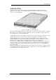
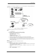
Introduction INTRODUCTION The Hypertec ISDN 10T Router is a compact router/bridge designed for small office and home applications by providing a consolidated data and voice link to Internet, Intranet, and the telephone network over a single ISDN line.
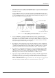
Introduction A schematic of how the Hypertec ISDN Router is used is shown in Figure 0-2 A Hypertec ISDN Router Application.
Introduction Security • CLID (caller ID) • Call-Back (hang-up and dial the caller) • PAP/CHAP ( PPP authentication protocol) • Access List (filtering of packets bases upon IP address) • NAT (network address translation). Hides internal IP addresses from outside world, no need to change existing IP address assignments, allows the subscription of single IP address account for the entire LAN. Network Management • From local console, NMS/SNMP or Web Browser/HTTP • NMS runs on Windows 3.
Introduction About this Manual Chapter 2, Installation. This chapter provides details of how to install the Hypertec ISDN Router hardware and software. Guidance is provided about the ISDN line that is required from your telephone company and the personal computer requirements to use the Network Management System software. Chapter 3, Concepts and Principles of Operation. This chapter covers the concepts and principles of operation of three major topics : ISDN, Data Services, and voice services.
Installation INSTALLATION General The Hypertec ISDN 10T Router is shipped in a box, which contains the following items: • • • • • • • • The Hypertec ISDN 10T Router One Power Adapter with cable One ISDN cable, 6 foot long with an RJ45 connector at each end One data cable with a DB9 connector at each end One changer DB9 (male) to DB25 (female) Two 31/2” diskette containing the Hypertec ISDN 10T Router NMS software One 31/2” diskette containing the Hypertec ISDN 10T Router EasyWeb software This Hypertec ISD
Installation 1. Determine the place where the Hypertec ISDN 10T Router is to reside, it is designed to rest on a flat level surface such as a desktop or table. Make sure that an AC power source and the ISDN termination are nearby. Connect the Ethernet LAN to any or all of the four RJ 45 ports labeled Ethernet using cables with RJ45 connectors.
Installation Software Installation The Hypertec ISDN 10T Router software diskettes contain two software packages, namely, NMS and EasyWeb. The Hypertec ISDN 10T Router Network Management System (NMS) is used to manage the Hypertec ISDN 10T Router from a Windows based PC equipped with a TCP/IP protocol stack.
Installation Uninstalling NMS Under Window95/NT you can uninstall NMS by selecting Add/Remove Programs in the Start/Settings/Control Panel window. Select NMS from the list and click the Add/Remove button. Installing EasyWeb The procedure for installing EasyWeb depends upon whether your system has an installed HTTP server or not. Installing EasyWeb if there is NO installed HTTP server. 1. 2. 3. 4. 5.
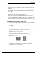
Installation Example using the Microsoft Personal web server on Win95. 1. Run the Microsoft Personal web server on Windows 95 2. Double click the icon on the right end of the task bar. A tagged Personal Web Server Properties) dialog box pops up. 3. Select the Administration page. 4. Press the Administration button to launch the default web browser on your system. 5. The Internet Services Administration web page is shown on the browser.
Concepts and Principles of Operation Physical Interface The ISDN physical interface is a available in two types, U and S/T. The S/T interface relies on a external device called NT1 to connect the user equipment to the ISDN line. The S/T interface is used in most parts of the world. The U interface, widely used in North America, is designed for user equipment with built-in NT1. The NT1 (also called ISDN DSU) built-in ISDN device is also allowed In Japan.
Concepts and Principles of Operation Directory numbers A directory number is the address or telephone number for the ISDN line assigned by your ISDN service provider or telephone company. The number of directory numbers allocated depends on which Service Provider you are using. If you are using an NI-1 line, you will be assigned one directory number per Bchannel. Otherwise, you will be assigned one directory number per device.
Concepts and Principles of Operation Service type DA64 DA128 Number of channels One B-channel Two B channels Data Communication Services Two widely used inter-networking mechanisms are bridging and routing. Bridging offers a straightforward method of interconnecting network segments. Bridges are simple to use. However, if you are bridging across a WAN using ISDN, you can incur unnecessary costs from the ISDN bill. A more controllable way of moving data cross networks is by routing.
Concepts and Principles of Operation Internet and Intranet Connection Profiles Hypertec ISDN 10T Router maintains two connection profiles one for Internet and the other for Intranet. The Internet connection by definition is for users to reach Internet, the Intranet connection is made between two offices. The Internet profile contains the configuration parameters required by the Internet connection. The categories available under Internet profile are : ISDN, PPP, IP, and NAT.
Concepts and Principles of Operation You can set Hypertec Router IP addresses to be 'un-numbered' or ‘numbered’. By setting it to “unnumbered”, you can route IP over a link between two devices without assigning IP addresses to the ISDN interfaces. This allows you to save valuable IP address space. There are situations where a traditional “numbered” IP address scheme is inevitable. In Figure 0-2, Unnumbered ISDN Link, there is an unnumbered link between an ISDN router and a remote router at the ISP site.
Concepts and Principles of Operation IPX IPX is the protocol used by Novel Netware as the network layer protocol. Novel IPX also uses Routing Information Protocol (RIP) for routing protocol. The IPX address consists of two parts: a 4byte network number, and a 6- byte node number. Often, the node number is assigned as the Ethernet MAC address. In a bridging environment, all Netware clients and servers share the same external network number.
Concepts and Principles of Operation RIP Novel IPX also uses Routing Information Protocol (RIP) as a routing protocol. Although it is similarly named to the IP equivalent, it uses a different protocol. IPX RIP broadcasts packets to the network every 60 seconds to inform other IPX routers or servers about its network. Upon receiving an IPX RIP packet, a router adds one to the hop count of each router advertised and broadcasts a RIP packet to other networks it is connected to.
Concepts and Principles of Operation Hypertec ISDN 10T Router to negotiate for either PAP or CHAP authentication protocol whichever the remote end prefers. Multilink PPP The PPP Multilink Protocol (RFC 1717) is a standards based extension of the PPP (Point-to-Point Protocol) standard. It allows you to combine channels into a 'Multilink bundle' so that data can be sent at higher rates.
Concepts and Principles of Operation Dial on Demand When the ISDN router receives packets from the Ethernet and decides to route packets to the WAN interface, an ISDN call is automatically made to the remote end, followed by the PPP negotiation. The PPP connection to the remote router is triggered automatically by the LAN traffic without user intervention.
Concepts and Principles of Operation diagram, traffic decreases temporarily before increasing again. Because bandwidth requirements can change suddenly like this, the second B-channel waits for a period of time before closing down. In the above diagram, this value has been set to 5 seconds. You can set this time to suit your own requirements. At point 4, data drops below the lower traffic load percentage value.
Concepts and Principles of Operation packets are to be filtered or forwarded. If no access list is specified, all valid packets will be forwarded. You can specify in the IP access list the following criteria: source IP address, destination IP address, source port number, destination port number, and the protocol which when matched will be forwarded or filtered. NAT The ISP generally offers two type of accounts to SOHO users. The Single User account, and the LAN Access (Multiple Users) account.
Concepts and Principles of Operation DHCP Managing IP addresses in an organization is often a headache for the MIS staffs. To ease the IP address management, the Dynamic Host Configuration Protocol (DHCP) is invented by IETF. DHCP protocol works in a client server configuration. One or more DHCP servers may be installed in the network. A workstation running DHCP client software (eg.
Concepts and Principles of Operation You must tell your service provider how you need the line configured for data, voice and other optional services. Your service provider needs to tell you: • the ISDN service and switch type • the ISDN directory (or phone) numbers • associated Service Profile Identifiers (SPIDs) (if required).
Concepts and Principles of Operation Provisioning the ISDN Line To make sure that you get the correct ISDN service for the Hyperte Router, you must tell your service provider how you need the ISDN line provisioned. This means whether you want data, voice or a combination of the two, what extra services you need and, possibly what terminal type you require.
Concepts and Principles of Operation Solution Sets Solution Sets have been created to correspond to a particular customer application. The Solution Sets appropriate to the Hypertec Router are: Solution Set Work at Home 3a ISDN Service Provides voice on one B channel and data on the other B channel. Includes ACO and CLI (Caller ID). Work at Home 4a Provides voice/data on one B channel and data on the other B channel. ACO and CLI are included.
Concepts and Principles of Operation Using Specific Switch Parameters Your service provider may require specific details about the parameters for the switch you are connected to. The parameters will depend on the service you are selecting. The following information provides the switch settings that are appropriate for the Hypertec Router connectivity.
Concepts and Principles of Operation When connecting to AT&T 5ESS Custom, you are provided with one telephone number (directory number). If you only need to connect one analog device (say a telephone) then one number is all that is required, but if you have two analog devices then you will need to subscribe to MSN. This will allow you to differentiate between the two analog devices and direct calls to the correct device.
Configura from a web browser are delivered to a software module called EasyWeb, which translates the HTTP requests into SNMP requests and forwards them to the Hypertec ISDN 10T Router. The ISDN router returns the SNMP responses to the EasyWeb which in turn translates them back into HTTP responses and forwards them back to the browser. The console offers the most fundamental user interface for router management.
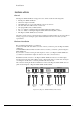
Configura The NMS menus are organized into a hierarchical structure shown in Figure 0-1, NMS Menu Structure: 24
Configura Login Quick Config Internet Internet Intranet Ethernet ISDN ISDN ISDN PPP PPP Ethernet IP IP IP Trace DHCP NAT IPX Local SNMP SNMP Statistics ISDN Bridge Figure 0-1, NMS Menu Structure The “Quick Config” menu provides a quick and easy way for users to configure the ISDN router for Internet Access. For straightforward Internet access, this menu is probably the only menu that is required.
Configura Figure 0-2, Example Sub-Menu window Figure 0-2 shows the window for the Internet sub-menu under the Quick Config main window. This is indicated by the bold lettering of the Quick Config main menu tab and the Internet sub-menu tab. Clicking in a field selects the field for entering a value. The selected field is indicated by a blinking insertion point (vertical bar). The Tab key can be used to tab to the next field and the Shift-Tab keys can be used to tab to the previous field.
Configura NMS System Menus In addition to the NMS menus, which are indicated by the tabs along the top of the displays, there are five System Menus which are listed along the very top of the window. These menus are File, Diagnostic, Product Info., View and Help. The File menu consists of: Save Config Load Config Download Config to Device Reset Config Load Code Recent Files Exit. The “Save Config” is used to save the router configuration to a file, which may be restored at a later time.
Configura NMS Toolbar NMS also includes a toolbar of four items which are displayed as four icons at the top right of the display. Figure 0-2, NMS Toolbar From left to right, these tools are: • Open a file • Save as • About NMS • Context sensitive help. Clicking this tool causes the mouse arrow to appear as a question mark. The user can position the question mark over a field and click the mouse to get help information about that field.
Configura Starting NMS In Windows 95/NT, NMS is started by clicking Start/Programs/Wishcom NMS. In Windows 3.1, NMS is started by clicking the NMS icon in the NMS window. Logging Into NMS The Login box pops up when you start the NMS program. The login dialog box serves two purposes: It lets you enter the IP address to select a specific Hypertec ISDN 10T Router to manage, it also lets you assign the IP address to an Hypertec ISDN 10T Router by clicking the associated check box.
Configura Quick Configuration Menu The Quick Config (see Figure 0-4, Quick Config Menu) is the first menu you will see after completing the login dialog box. There is only one sub-menu, Internet, for Quick Configuration menu. If you have successfully logged into the router, you should see most fields in this page containing data; if this is not the case, it indicates communication problems between NMS and the Hypertec Router. See diagnostics hints in Chapter 5 if you run into such a problem.
Configura Local IP Address The local IP address is the IP address assigned to this router. The IP address is entered in the standard IP address format of a.b.c.d. The local IP address is required during the PPP negotiation. Please ask your ISP if you don’t possess one, unless you have a connection with dynamic IP address allocation. You would need to reset the router if this field gets changed. Local IP Mask The local IP mask is used to describe the local IP sub-netting.
Configura ISDN Switch Type The ISDN switch type specifies the type of ISDN switch to which your ISDN line is connected. The pull down the "switch-type" menu, and select the one right for your ISDN line. The ISDN switch type has to be correctly selected in order for your ISDN router to synchronize with the telephone company’s ISDN switch. Please check your local phone company for the exact switch type. In Northern America, the dominant switch type is National ISDN-1 (NI-1).
Configura Dial-out Authentication The dial-out authentication field specifies which protocol you want to run as the PPP/MLPPP authentication protocol when you initiate an ISDN call to your ISP. Most ISPs support PAP and CHAP protocols. Dial-out Password The dial-out password specifies the password to use during the dial-out authentication process. This field is case sensitive, and is given to you by your ISP.
Configura Figure 0-5, Local Ethernet Window Device Name The device name specifies the name of this ISDN router. This field is linked to Local Router Name in the menu “Quick Configuration”. Any text character is acceptable for up to 32 characters. IP Address The IP address describes the IP address assigned to this router by your ISP. This field is linked to Local IP Address in menu “Quick Configuration”. IP Mask The IP mask describes the local IP sub-netting.
Configura Figure 0-6, Local ISDN Window SPID 1 In Northern America, the local phone company assigns two SPIDs for each ISDN line. This field should be ignored for users outside Northern America. Please refer to explanation under “Quick Config”. SPID 2 In Northern America, the local phone company assigns two SPIDs for each ISDN line. This field should be ignored for users outside Northern America. Please refer to explanation under “Quick Config”.
Configura Phone 1 Usage The phone 1 usage specifies the which SPID the phone 1 is associated with. This field is ignored by users outside Northern America. Phone 2 Usage The phone 2 usage specifies which SPID the phone 1 is associated with. This field is ignored by users outside Northern America. Data Usage The data usage specifies which SPID(s) the data connection will be associated. This field is ignored by users outside Northern America.
Configura Route Table Figure 0-7, Local IP Window Access List The access list is a filtering table for security application. You may selectively filter or forward certain packet according to its source IP address, protocol, destination IP protocol, and destination port number. For example, if you intend to block a web page being retrieved from a certain web server, you may create an entry for that particular IP address in the access list table to deny its traffic.
Configura Local DHCP Sub-menu The DHCP sub-menu contains the DHCP parameters which describe how the Hypertec Router as a DHCP server operates, and what TCP/IP configuration information to release. IP Address Pool (Start Address, End Address) The IP address pool as indicated by the Start Address and End Address is used by the DHCP server to release the IP addresses to the DHCP clients. The Hypertec Router supports 16 IP addresses even if user specifies a IP address pool larger than 16 IP addresses.
Configura Domain Name While leasing an IP address to a client, the domain name configuration information is also available from the Hypertec Router DHCP server. Lease Duration The lease duration describes the maximum time length the IP address is leased to a client. A client usually renews the IP address half way before the lease duration expired. The maximum lease duration is 100 days. The minimum lease duration is 1 day even if a duration of less than one day is entered.
Configura Figure 0-8, Internet PPP Window Remote Router Name The remote router name is the name assigned to the remote router located at the ISP end. Any visible ASCII characters are acceptable. The remote router name is not required when you want to dial into your ISP’s point of presence. In general, your ISP assigns to you a remote IP address for administration purpose. Compression The compression field specifies if the Stac compression protocol will be turned on for the Internet connection.
Configura Call-in Authentication The call-in authentication field specifies which protocol you want to run as the PPP/MLPPP authentication protocol when the ISP initiates an ISDN call to you. Under normal circumstances your ISP will not initiate a call to you. Call-in Password The call-in password specifies the password to use during the call-in authentication process. This field is case sensitive, and is given to you by your ISP.
Configura Internet IP Sub-menu The Internet IP sub-menu (see figure 0-11) is used to configure the IP related parameters of the Internet connection. For most Internet application, the un-numbered interface based configuration is appropriate. You need only to specify a remote IP address, instead of a pair of IP addresses for local end and remote end of the IP connection. Remote SNMP Enable This check box is to enable or disable SNMP management from remote.
Configura IP Mask of Remote Ethernet The remote IP mask is used to describe the remote IP sub-netting. The IP mask is entered by clicking the IP address bit map. The number of bits assigned for the IP subnet is shown next to the IP address bit map as a decimal number, for your reference. Local End IP Address of ISDN Line This field specifies the local end of the IP address of an IP connection. This field is applicable to the “numbered interface” IP address setting.
Configura Network Address Translation Enable This field enables or disables the NAT function. Starting Port This field specifies the starting port number NAT would use to support the NAT function. 1024 is the default port number. FTP Server The internal IP address of the FTP server that provides FTP service to the outside world. All incoming FTP service requests are routed to the specified FTP server. HTTP Server The internal IP address of the HTTP server that provides HTTP service to the outside world.
Configura Preemption Allowed This field is specified if the Internet connection is allowed to be preempted by a phone call or not, and in what way. The Internet connection can be blocked from preemption at all, or be allowed on the 2nd PPP only, or 1st PPP as well. Figure 0-11, Intranet ISDN Window CLID Caller ID can be used to qualify the incoming call. Only the incoming call whose calling number matches the CLID will be accepted. This is an Intranet feature.
Configura The Intranet PPP sub-menu is shown in fig 4.14. This menu is used to configure the PPP parameters for an Intranet connection. Figure 0-12, Intranet PPP Window Remote Router Name The remote router name is the name assigned to the remote router located at the ISP end. Any visible ASCII characters are acceptable. The remote router name is not required when you want to dial into your ISP’s point of presence. In general, your ISP will assign you a remote IP address for administration purpose.
Configura Encapsulation Protocol The encapsulation protocol field specifies the protocol you want to run as the link protocol. Select PPP if you want to run single channel PPP. Select MLPPP if you intend to run two channel PPP when traffic becomes heavy. Dial-out Authentication The dial-out authentication field specifies which protocol you want to run as the PPP/MLPPP authentication protocol when you initiate an ISDN call to your ISP. Most ISPs support PAP and CHAP protocols.
Configura 2->1 Util The 2->1 Utilization specifies the Intranet connection traffic level; below which the second PPP channel will be released from the PPP bundle. The value ranges from 0% to 100%. This parameter is available only if the MP protocol is selected as the Internet encapsulation protocol. 1->0 Idle The bandwidth management function will remove the (primary) Intranet connection when it is being detected idle for a specific period. The 1->0 Idle parameter specifies the idle period in seconds.
Configura This parameter is used to enable or disable the IP routing function. If IP routing is disabled, bridging must be enabled for IP packets to be forwarded through the router. Bridging is rarely used as the protocol for Internet access. IP Address of Remote Ethernet The remote IP address is the IP address of the remote router located at your ISP site. The IP address is entered in the standard IP address format of a.b.c.d. The remote IP address is required during PPP negotiation.
Configura Figure 0-14, Intranet IPX Window RIP The IPX RIP packets will always be exchanged over the WAN when the ISDN connection is up. The RIP box when checked is to allow Netware RIP traffic to initiate the ISDN connection. This is not advised as it will lead to unnecessarily high ISDN connection charges! SAP The IPX SAP packets will always be exchanged over the WAN when the ISDN connection is up. The SAP box when checked will allow Netware SAP traffic to initiate the ISDN connection.
Configura Spoofing The check box to enables or disables the IPX spoofing function. The spoofing function minimizes the dial-up connection time by responding to the “keep alive” request on behalf of the remote IPX clients. The spoofing function tries to minimize the ISDN dial-up against the IPX “keep alive” messages but does not inhibit the the regular IPX or SPX messages.
Configura SNMP Menu The SNMP menu (see Figure 0-15, SNMP Window) is used to configure the SNMP specific parameters. Some of the parameters are corresponding to the objects defined in the system MIB. The rest are for managing the SNMP access, and trap delivery .
Configura Description The field gives a brief description of the product, as provided by the manufacturer. Name This field is used by the user to assign a name to this ISDN router. Location This field is used by the user to describe the location of this ISDN router. Contact This field is used by the user to describe the contact person for the ISDN router. Read Community This field is used to assign a “password” for SNMP read operation.
Configura This counter displays the number of frames the Ethernet has received or transmitted. Broadcasts This counter displays the number of broadcast frames the Ethernet has received or transmitted. Figure 0-16, Statistics Ethernet Window Errors This counter displays the number of error frames the Ethernet has received or transmitted. The error conditions are : too short, mis-alignment, excess collision.
Configura Discards This counter displays the number of frames the Ethernet has discarded due to lack of buffer resource or error detection.. Statistics ISDN Sub-menu The Statistics ISDN menu (see Figure 0-17, Statistics ISDN Window) contains the statistics and status data collected on the ISDN interface. The “refresh” button is used to collect a new page of statistics data. The “periodic on” button is used to refresh this menu every second.
Configura B Channel(s) Up Time This field display the time the ISDN channels, B1 or B2, have stayed up since last reset. Both channels up for 1 minute is counted as 2 minutes. B Channel(s) In Use This field displays the percentage of time the B channel, B1 or B2, has stayed up since last reset. 50% in use may mean one B channel is up all the time, and the other B is down all the time or both channels are up for 50% of the time. 100% in use means both B channels are up all the time.
Configura Trouble Shooting Under the Detail Log, the trouble shooter enables the ISDN router to send more detailed IP, PPP, and ISDN activity traps to NMS to enable trouble shooting. It should only be enabled during the trouble shooting stage. Keeping it on all time will increase the Ethernet traffic, and work load to the ISDN router and therefore is not beneficial to performance. Clear Trap List This click button is used to clear the traps previously stored in the trap history.
Configura ISDN Data Call Success This field displays how many times the ISDN router has succeeded in making ISDN data calls since last reset. Note that an incoming ISDN data call does not contribute to this counter. PPP Attempts This field displays how many times the ISDN router has tried to negotiate PPP data connections since last reset. PPP Success This field displays how many times the ISDN router has succeeded in negotiating PPP data connections since last reset. Monitoring Status with ClearMon.
Configura Figure 0-20, Console Login Screen The login screen allows users to enter a password. The default password is “isdn”. Users are urged to set up a new password, up to 16 alphanumeric characters, using “F2 Change User Password”. When the password has been successfully entered, press the Enter key to display the console quick config screen as shown in Figure 0-21, Console Quick Config Screen.
Configura Figure 0-21, Console Quick Config Screen The Console Quick Config screen permits the user to enter configuration data. Use the Tab key to move to the next field and the Shift-Tab key to move to the previous field. The Route Table data can be seen by pressing the F2 key and Statistics data by pressing the F3 key. The F4 key is used to exit a screen.
Configura Figure 0-22, EasyWeb SNMP Manager Troubleshooting This chapter explains how to isolate and resolve simple problems encountered with the Hypertec ISDN Router. Problems may stem from incorrect configuration setting or improper installation. Follow the following steps should help you resolve most of the symptoms. If problem persists, please contact your technical support with a list of symptoms, LED display status.
Troubleshooting Troubleshooting Tips Before you call technical support organization for assistance, check the following : 1. The power supply is connected and the power LED is on. 2. Turn the power off and on again, observe the alarm (ALM) LED During power-up self-test, the ALM LED flashes. If the ALM LED flashes and remains on for more than 10 seconds, there is an internal hardware failure. Notify your reseller that the ISDN router has failed the self-test, and order a replacement.
Troubleshooting 4. Monitor the status of the D channel LED When you are connected to a live ISDN line, the D channel LED will be lit or flashing. If the D channel LED remains off, it indicates that no ISDN signal present. It is likely that there is a poor connection to the local telephone company. Make sure that the ISDN cable is in good condition, and securely plugged-in. If the LED remains off, call your local telephone company for trouble shooting assistance.
Troubleshooting 8. If your are unable to communicate with the router through NMS. The Network Management System (NMS) communicates with the router through Ethernet using the SNMP protocol. If your NMS is unable to get SNMP response from the router, check the following : Ping a known active station in the local Ethernet. If you are unable to receive the ICMP response, you may have problem with your TCP/IP installation. Check the NMS Ethernet cable, NIC, and TCP/IP configuration.
Index contact .......................................................... 4-35 D data compression .......................................... 3-12 data service field.................................. 4-18, 4-24 data usage ..................................................... 4-14 device name.................................................. 4-11 dial-on-demand............................................. 3-11 dial-out authentication.........4-9, 4-10, 4-20, 4-28 dial-out password ................
Index phone number-1............................................ 4-13 phone number-2............................................ 4-14 Point-to-Point Protocol (PPP) ........................ 3-8 PPP ................................................................. 3-8 preemption allowed ............................. 4-18, 4-24 Provisioning ISDN ....................................... 3-15 Q quick configuration menu............................... 4-7 R Rate Adaptation.........................................
Index Product Warranty Hypertec Limited warrants the hardware components of the product to be in good working order for the life of the product from the date of purchase of the product from Hypertec or an authorised Hypertec dealer. Should the hardware components of the product fail to be in good working order at any time, Hypertec will, at its option, repair or replace the product. Repair parts and replacement products will be furnished on an exchange basis, and will be either reconditioned or new.