
Data Sheet
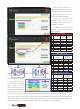

Vengeance 5.8Ghz Channel
Group/
Channel
Channel 1 Channel 2 Channel 3 Channel 4 Channel 5 Channel 6 Channel 7 Channel 8
Group1 (A) 5740 5760 5780 5800 5820 5840 5860 5880
Group2 (B) 5705 5685 5665 5645 5885 5905 5925 5945
Group3 (C) 5865 5845 5825 5805 5785 5765 5745 5725
Group4 (D) 5658 5695 5732 5769 5806 5843 5880 5917
Group5 (E) 5733 5752 5771 5790 5809 5828 5847 5866
Hyperion FXT 5.BGHz 40 Channel AV Transmitter
Modulate Wideband FM Modulate
Video Format NTSC / PAL
Characteristics
Value Units
Min. Typ. Max.
1 Output Impedance --- 50 --- Ohm
2 Output Power
FX795T-L/ 25mW 12 13 14 dBm
FX795T-2/200mW 22 23 24 dBm
3 Frequency Range 5645-5945 Mhz
4 Operating Voltage 7.0 12 20 V
5 Supply current
FX795T-L/ 25mW - 70 - mA
FX795T-2/200mW - 200 - mA
6 Output Voltage(VOUT) VOUT=5V V
7 Operating Temperature -10℃ --- +85℃
8 Video Band Width 0 --- 8.0 Mhz
9 Audio Carrier Frequency --- 6.5 --- Mhz
10 Video Input Level 0.8 1.0 1.2 Vp-p
11 Video Input Impedance --- 75 --- Ohm
12 Audio Input Level 0.5 --- 2.0 Vp-p
13 Audio Input Impedance 10K Ohm
14 Weight --- 7.5 --- Gram(s)
15 Antenna Connector SMA Female Connector
16 Dimensions (L x W) 31x22mm
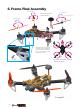
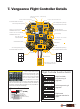
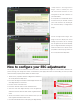
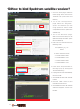
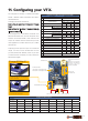
11. Conguring your VTX.
Channel button
Long press:Change Group
Short press:Change Channel
25mW/250mW Change
↑When the "mode change wire"
is not cut the VTX will transmit in
25mw. (Default)
↑To output in 250mw power you
must cut the "rf limit wire".
Microphone
Antenna Connection
Jack:
NOTE: Do not power
ON your Vengeance
without the VTX
Antenna installed.
Group LED
Channel LED
DC7~24V in GND Video in GND DC5V out
Change RF Output?
Cut this wire
The Vengeance utilizes a 5.8GHz Selectable
25mW / 250mW Video Transmitter with 40Ch's
with Raceband.
Changing Channels and Bands:
Push button for more than 2 Seconds: Change
Band.
Push button for less than 1 Second: Change
Frequency Channel.
The Vengeance's VTX utilizes a 25mW and
250mW selectable VTX. In most European and
Western Countries 25mW is the maximum Rf
output for 5.8Ghz. Please check with your law
and regulations to make sure that you conrm
with the law.
Adjusting the Rf power output for increased
range. You may cut the "RF limit wire" so that
you may transmit at 200mW power. If you wish
to later transmit at 25mW you may solder the
"RF limit wire" again.
17