
Data Sheet
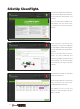
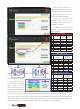

The colored indication bars
in CleanFlight represent
your real time channel PWM
signal. Make sure to turn
your Transmitter ON so you
may check your trim and to
make sure your channels moves in the correct direction.
It is important to note that when you move your Transmitter sticks that your Transmitters Travel Adjustment (ATV)
must move to less than 1100 and more than 1900. If your Transmitters Travel Adjustment is not properly setup
than your Vengeance will not ARM. To ARM your Vengeance move your YAW/RUDDER stick to the Bottom and
RIGHT position for 1-2 seconds. DO NOT ARM Vengeance with propellers on for the rst time!
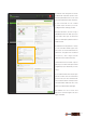
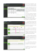
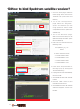
The "Receiver" directory of
CleanFlight helps to show you your
Channel Map and the position
of your Transmitters controls with
respect to the Flight Controller.
Under the "Channel Map"
option please choose if you
are using Futaba / Hitec or JR /
Spektrum / Graupner.
DO NOTE! You must "Save and
Reboot" to save changes onto your
ight controller.
MODE 1
Throttle
Roll
Pitch
Yaw
MODE 2
Throttle
Roll
Pitch
Yaw
Channel Map
Default
Futaba
Hitec
JR
Spektrum
Graupner
1 Roll Roll Throttle
2 Pitch Pitch Roll
3 Throttle Throttle Pitch
4 Yaw Yaw Yaw
5 Aux1 Aux1 Aux1
6 Aux2 Aux2 Aux2
7 Aux3 Aux3 Aux3
8 Aux4 Aux4 Aux4
Radio Channel Revers
Futaba
Hitec
JR
Spektrum
Graupner
1 Roll Reverse Throttle Normal
2 Pitch Normal Roll Reverse
3 Throttle Reverse Pitch Normal
4 Yaw Normal Yaw Reverse
5 Aux1 Aux1
6 Aux2 Aux2
7 Aux3 Aux3
8 Aux4 Aux4
Radio End Point / ATV Setting
Futaba
Hitec
JR
Spektrum
Graupner
1 Roll
110/110%
Throttle
120/120%
2 Pitch
110/110%
Roll
120/120%
3 Throttle
110/110%
Pitch
120/120%
4 Yaw
110/110%
Yaw
120/120%
5 Aux1
110/110%
Aux1
120/120%
6 Aux2
110/110%
Aux2
120/120%
7 Aux3
110/110%
Aux3
120/120%
8 Aux4
110/110%
Aux4
120/120%
Left
Left
Pitch UP (Stick Low)
Low
Gimbal DOWN
Flight Mode Change Flight Mode Change
Gimbal UP
Right
Right
Pitch Down (Stick Hight)
High
12