
User manual
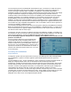
for tuning. Now turn the pot until the flight pack battery voltage shown on the transmitter screen
agrees with the value measured using an accurate voltmeter.
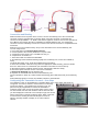
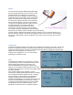
2. Receiver Voltage: Again briefly touch the RPM wire to the middle pin of the bind connector.
The red LED should start to flash. Turn the pot until the receiver voltage shown on the
transmitterscreen agrees with the value measured using an accurate voltmeter.
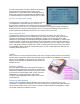
3. Flight Battery Current: Again briefly touch the RPM wire to the middle pin of the bind
connector. The green and red LEDs should start to flash. Turn on the motor with throttle STi™ck
while measuring the current with an external meter. BEWARE of the spinning propeller! 5
For maximum accuracy, and because of fluctuations in the reading, it is advisable to calibrate
the unit at as high a current as you can reliably measure, or at least in the general range of
current
you are interested in measuring. For instance a variation of 0.3 Amps at 3 Amps is an error of
10%, but at 30 Amps it is only 1%. Any error will be in both the current display and the mAh
consumption figure. Go to the "PowerBox™" page on the transmitter display6 and check the
reading on "Capacity 1". The numerical value shown as mAh is actually the reading for current
in mA. The value will flicker as the display toggles between minimum resolution output values.
This is an inherent limitation of the measuring circuit in the telemetry unit. Note that if you
connect to a load that draws more than about 4 Amps, the display may initially appear as zero.
This may be because the pot is STi™ll fully clockwise and at maximum sensitivity and
the display is off the scale. Rotate the pot anticlockwise until the telemetry reading matches as
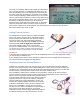
closely as possible the value shown by your meter. For example, if your current meter reads
22.0 Amps, turn the pot on the telemetry unit to show as close as possible to 22000 on the
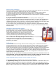
transmitter PowerBox™ screen. Do not expect to match more closely than about 0.2-0.3 Amps.
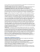
In the example below the Hyperion Emeter on the left is reading 22.0 Amps while the closest
steady reading was 22.223 Amps. Shut down the motor and turn off the telemetry unit. Move the
pot/switch to the middle position and power on again to resume normal operation. Not available
on DX6™ and DX7s™ transmitters.
IMPORTANT: The calibration system will loop through the three states in turn, so if you skip
one by accident, just repeatedly touch the center bind pin with the wire until you reach the one
you want. However any time you enter a calibration (flashing LED) mode the range is set to that
pot position. The result is that you cannot just calibrate a single function by jumping to that
function without re-doing the others. For example, if you go to current calibration you will have
gone through Flight Battery Voltage and Receiver Voltage to get there and those voltages will
have been recalibrated to whatever the pot position had been for the current calibration.
Bottom line: If you do a calibration then the display must be actively set to the correct value for
each one of the three variables every time you select a variable (Flight Battery Voltage,
ReceiverVoltage, Flight Battery Current). The telemetry unit stores the last calibration value it
sees when the LED(s) were flashing.
Appendix: Calibration choices
The effect of the options described below is small. Users can ignore this section unless
looking for maximum accuracy in setting alarms.
For greatest accuracy in alarm behavior, it is necessary when adjusting the display readout to
choose how you want the resolution limits to work. This is not a Hyperion calibration issue but a
consequence of the way in which Spektrum™ transmitters display the numbers.
Current calibration is limited by display fluctuation at minimum resolution. The pack and receiver
voltage, however, are only displayed to a resolution of 0.1V which is greater than calibration
accuracy. Consequently, you need to choose between “mid point”
calibration and “lowest limit” calibration if you are concerned about precision.
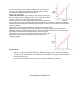
Mid-point calibration. The chart at right shows what is normally understood by calibration and is
technically the truest representation of the voltage within the limit of the display. The output follows