
User manual

Current sensor calibration
The current sensor is calibrated at the factory and will not normally need attention. If for any reason
you swap current sensors or replace one, then you need to reinitialize
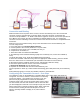
it to remove any offset. Expose the pot/switch and have a small screwdriver ready to adjust it.
1) Bind the telemetry unit to the transmitter with a suitable receiver, as explained earlier.
2) Upon successful binding, power off the telemetry/receiver unit but leave the transmitter turned on.
Remove the bind plug.
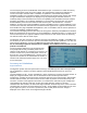
3) Turn the pot/switch fully clockwise (to the right).
4) Plug the V/I sensor (and Temperature/RPM sensor if required) into the telemetry unit.
5) Power on the telemetry with a flight pack attached to the sensor. The green LED should become
steady on within no more than 3 seconds. This indicates the current sensor's bias calibration is
completed successfully. If the red LED is on, the unit has failed to calibrate and you should try again
from the beginning. If bias calibration remains unsuccessful, the unit is faulty.
6) Turn off power to the receiver/telemetry unit. Adjust the pot/switch to approximately the middle
position and power on again to resume normal operation. The green LED should then flash twice a
second as usual.
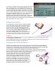
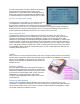
Changing to absolute altitude readout
As explained above, the unit as supplied shows height above
ground level (AGL), as this is what nearly all fliers understand by
model height. A ground level of zero is set every time power is
connected to the telemetry unit. If for any reason you want
readout in absolute pressure altitude above sea level (ASL),
rotate the pot/switch fully anticlockwise with power off and leave it
there. The green LED will now be absent rather than flashing
twice a second. Since the displayed height is based on a standard
sea level pressure of 1013.25 kPa, for an accurate altitude
reading you will need to apply a correction for current barometric
pressure at your location.
Calibration
The unit is calibrated at the factory and most users will simply use it as delivered. However the
firmware allows the user to "fine tune" the span value of the battery voltage and receiver voltage to
the absolute correct level. The current and consumption values can also be calibrated against a
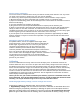
known accurate wattmeter or high current ammeter. By enabling "calibration" mode on the telemetry
unit, you can use the pot hidden under the label to adjust the value displayed on the telemetry
screen in real-time to match that of an accurate meter. Once calibrated, the span value will be saved
in EEPROM, thus ensuring accurate measurement. See the Appendix for a discussion of how the
limited display resolution might affect this.
Unless you are sure you need to recalibrate your telemetry system it is advisable to leave the
unit as delivered. If you do not understand the process, and fail to follow the directions below
carefully, it is easy to introduce large errors in any one of the three values.
Calibrating flight battery voltage, receiver voltage and current
First bind and calibrate as described under “Current sensor calibration”
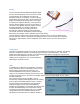
1. Flight Battery Voltage: After successful Current sensor calibration as described above and
without moving the pot (Still fully clockwise) or allowing the power to be interrupted, touch the
RPM wire (red wire) briefly to the middle pin of the bind connector. Be careful not to short the
pins! The green LED should now be flashing, which indicates that the battery voltage is ready