
User manual
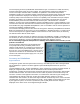

The second plug-in sensor (available with either Deans™-style T-connectors or XT60 connectors)
measures flight power pack current and voltage. The instantaneous readings are displayed on
screen in the Amps and Volts fields. In addition, on Spektrum™ transmitters that provide a
PowerBox™ display, the cumulative number of mAh drawn from the flight pack and the pack voltage
at higher resolution are displayed. The displays may vary depending on the fields chosen in
Telemetry Setup in the transmitter menu and on the capability of the transmitter itself (for example,
the DX6™ and DX7s™ do not display PowerBox™). The telemetry unit works with any various
brands DSMX™ protocol receiver that has bind connector pins. This includes the 7-channel
Stabilizer, as well as the 6-channel DSMX™ protocol compatible receiver. Various Spektrum™ and
receivers have also been tested and found to work with the Hyperion unit. Hyperion also states that
their satellites are plug-compatible with Spektrum™, but it is sensible to test the correct operation of
receivers and satellites of different brands.
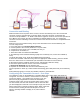
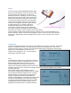
The connection lead plugs into the data socket of the Hyperion Telemetry unit (labeled “To Receiver
Bind”) and the bind port of the receiver, just as the Spektrum™ TM1000 unit does. A Y-cable can be
used on the bind pins of a Hyperion stabilizer if that connector is also used for Aux2; the telemetry
unit will not interfere with the Aux2 output.
The Hyperion unit does not have an X-BUS™ port and is not Spektrum™ X-BUS™ compatible. Nor
are the three pin JST-ZH connectors (the four small white ones) wired like Spektrum™. For this and
other reasons, Spektrum™ sensors are NOT interchangeable with Hyperion sensors.
Do not interchange Hyperion and Spektrum™ telemetry unit hardware and connectors, as the
polarities are different.
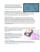
The unit has been designed on the assumption that
most people will be using a 5V BEC power source.
However it will operate on a voltage of from 3.45 to 7.2V
from the receiver. So in practice this power source can
be a 1S LiPo, a 4 or 5cell NiMH pack, a 2S LiFe pack, a
separate 5 or 6V BEC or the internal BEC of an ESC. It
should not be used with a power supply over 7.2v, such
as a 2s LiPo pack.
Accuracy and Limitations
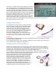
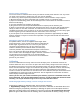
Signal Indicator
The Hyperion system does not report Frame Losses (F) and Holds (H) since this is data generated
only by Spektrum™ systems. Nor does Hyperion report individual packet losses on up to four
separate
receivers/satellites (A, B, L and R) as Spektrum™ does. However the Hyperion unit does use the “A”
display for a Signal Indicator value. This is calculated from the number of packets lost in
transmission. A reading of 100 means that no packets have been lost in transmission, while smaller
numbers indicate losses. The value is based on the number of packets received about every half
second. In versions of the Hyperion unit to date, it is of limited use and tends to give readings that
range between 85 and 100. Note that, as with some other telemetry systems, if the data
communication link is broken, the last known Signal Indicator value will stay on the screen until data
communication is restored. As noted previously, the B, L and R satellite receiver fields are not used
by the Hyperion system, nor are the F (Frame loss) and H (Hold) fields. Receiver voltage is
displayed on the same screen as the Signal Strength indicator.