
User manual

and some user variables. Note that the FlightLog™ field alarms
are not used by Hyperion. The Settings field allows you to set
when the telemetry screens are displayed, the units used, plus
the name of data logs and how they are started. In the Settings
screen setting the Display to Roller means that you can use the
roller to scroll through the telemetry screens at any time from the
normal main Transmitter display screen; this is very convenient.
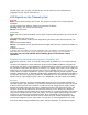
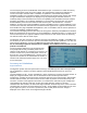
Exit back to the MAIN screen when you are finished. As
explained under Signal Indicator on page 6, the “A” field under
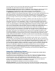
Flight Log will provide a basic measure of signal reception. If
your receiver is powered up, properly bound, and the telemetry unit is connected, you will see the
bars logo marked on the screen at right.
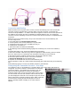
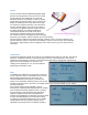
Adding External Sensors
The Voltage/Current sensor and/or the Temperature/RPM
sensor can now be connected to the appropriate sockets
on the Telemetry unit (with power off). The EXT socket is
reserved for future use. After connecting an external
sensor, the receiver and telemetry unit must be re-bound
to the transmitter, with the flight pack connected in the
case of the Voltage/Current sensor. Use the same
process as in Getting Started – First Time Use on page 2.
The examples show a DX8™ transmitter. Other transmitters may
have different displays, but the principles of setup are similar.
WARNINGS:
1) Do not plug the Voltage/Current sensor into the Temp/RPM socket. If you then apply pack voltage
you may destroy the telemetry unit.
2) The Voltage/Current sensor can be damaged if subjected to reverse voltage. Check the polarity of
the connections before plugging in the flight battery.
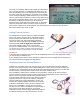
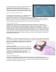
Displaying Data from External Sensors
Configure the transmitter screens to show the values you are interested in from these additional
sensors. As we saw previously, there is little flexibility in the screens as they have been largely pre-
configured. The current/voltage sensor will display the instantaneous pack voltage in the Volts field
and total current in the Amps field. Alarms can be set for Min and Max values.
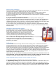
If the PowerBox™ (PBox) field is available on your transmitter, voltage can be shown to higher
accuracy and the cumulative number of mAh consumed can be displayed. If these values do not
appear, check that you have activated (Act) the PBox display
in the transmitter Telemetry setup screen. Note that with the
Hyperion unit there is only one set of battery voltage and
capacity readings (the original PowerBox™ sensor unit
monitors two separate supplies) and there are NO alarms
available for PowerBox™ values, as these depend on the
presence of a PowerBox™ sensor unit. The practical
outcome is that no alarm is available for the percentage of
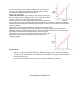
pack capacity used. When plugged in, the external
temperature sensor (shown at right) automatically replaces
the internal telemetry unit value with the more accurate