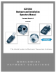
ICE 5700 Hardware and Installation Operators Manual Document Revision A 04-04-2001
Hypercom Corporation 2851 West Kathleen Road Phoenix, Arizona 85053 USA Corporate Telephone: 602.504.5000 Corporate Fax: 602.866.5380 Corporate Repairs Department: 602.504.5378 Corporate Web Site: www.hypercom.com Copyright 2001 by Hypercom Corporation. Printed in the United States of America. All rights reserved. This publication is proprietary to Hypercom Corporation and is intended solely for use by Hypercom customers.
FCC Part 15 (ICES-003) This equipment has been tested and found to comply with the limits for a Class A digital device, pursuant to Part 15 of the FCC (ICES-003) Rules. These limits are designed to provide reasonable protection against harmful interference when the equipment is operated in a commercial environment.
Industry Canada (IC) Notice NOTICE: The Industry Canada (IC) label identifies certified equipment. This certification means that the equipment meets telecommunications network protective, operational, and safety requirements as prescribed in the appropriate Terminal Equipment Technical Requirements documents. The department does not guarantee the equipment will operate to the user’s satisfaction.
Table of Contents Table of Contents List of Figures List of Tables Introduction Guide Organization . . . . . . . . . . . . . . . . . . . . . . . . . . . . . . . . . . . . . . . . . . . . . . . . . . . . . . . . . . . . . . . . . . . . . . . . . . . . . . . xiii Who Should Use This Guide . . . . . . . . . . . . . . . . . . . . . . . . . . . . . . . . . . . . . . . . . . . . . . . . . . . . . . . . . . . . . . . . . . . . . . . . xiii Other Documentation . . . . . . . . . . . . . . . . . . . . . . . . . . .
Table of Contents Chapter 4 Wireless POS Terminal Interface Function Blocks . . . . . . . . . . . . . . . . . . . . . . . . . . . . . . . . . . . . . . . . . . . . . . . . . . . . . . . . . . . . . . . . . . . . . . . . . . . . . . . . . 4-1 Operation . . . . . . . . . . . . . . . . . . . . . . . . . . . . . . . . . . . . . . . . . . . . . . . . . . . . . . . . . . . . . . . . . . . . . . . . . . . . . . . . . . . . . . 4-2 Instructions to the User . . . . . . . . . . . . . . . . . . . . . . . . . . . . .
List of Figures List of Figures Chapter 1 Hardware Information Figure 1-1. ICE 5700 terminals . . . . . . . . . . . . . . . . . . . . . . . . . . . . . . . . . . . . . . . . . . . . . . . . . . . . . . . . . . . . . . . . . . . . . . 1-1 Figure 1-2. Standard keyboard . . . . . . . . . . . . . . . . . . . . . . . . . . . . . . . . . . . . . . . . . . . . . . . . . . . . . . . . . . . . . . . . . . . . . . 1-3 Figure 1-3. Touch-screen display . . . . . . . . . . . . . . . . . . . . . . . . . . . . . . . . .
List of Tables List of Tables Chapter 1 Hardware Information Table 1-1. Terminal dimensions . . . . . . . . . . . . . . . . . . . . . . . . . . . . . . . . . . . . . . . . . . . . . . . . . . . . . . . . . . . . . . . . . . . . . 1-6 Chapter 2 Installation Procedures Table 2-1. Self-test and diagnostics with software loaded . . . . . . . . . . . . . . . . . . . . . . . . . . . . . . . . . . . . . . . . . . . . . . . . . . 2-4 Table 2-2. Memory page states . . . . . . . . . . . . . . . . . . . . . . . . .
Introduction The ICE 5700 Hardware and Installation Operators Manual is a comprehensive guide to working with Hypercom® ICE 5700 terminal. The ICE 5700 terminal is part of the Hypercom Interactive Consumer Environment (ICE) family of touch-screen-based terminals and peripherals. All ICE terminals support traditional terminal functions as well as PIN pad and signature capture functionality. The ICE family employs a modular concept.
Introduction Guide Conventions This section provides information to help you understand the procedures and concepts presented in this guide. The following special terms and style conventions are used throughout this document: Component names: Special bold text highlights certain items including the names of window and dialog box components. This text appears in instructions for specific actions such as clicking buttons, typing in text boxes, and selecting from lists.
Introduction Series of actions: The greater-than sign (>) appears in procedures indicating a series of simple, related actions using the mouse pointer. The resulting action typically starts a utility or opens a dialog box. For example From the Term-Master main menu, click Network > Definitions’. Caution and Warning boxes: When you see a Caution or Warning message, read the information promptly and carefully before proceeding. The formats for the boxes follows.
C h a p t e r 1 7 Hardware Information This chapter provides important information to properly set up and test both the ICE 5700 terminal. To prevent damage to the POS terminal and possible personal injury, be sure to read this document before installing an ICE terminal. Figure 1-1.
Chapter 1 General Safety Precautions This section describes general safety precautions that must be followed to ensure proper installation and maintenance of the POS product family. C AUTION Electrical Safety: Observe all normal electrical safety practices when operating any equipment attached to an active power source. Authorized Service: Only a Hypercom authorized service technician or an authorized repair station can perform equipment servicing, adjustment, maintenance, or repairs on the POS products.
Hardware Information Security Tamper resistance is provided through the use of intrusion detectors and a secure CPU/RAM module that is housed in a sealed metal case. PIN encryption, MAC-ing, encryption key storage, and management are performed in a separate secure co-processor with its own internal RAM. The ICE 5700 terminal supports as many as four integrated Security Access Modules (SAMs) for various smart card solutions. Keyboard The keyboard consists of 12 keys: 10 numeric and 2 control keys.
Chapter 1 Touch-Screen Display The ICE 5700 terminal is built around a graphic touch-screen that provides a high degree of flexibility and an intuitive user environment. Additionally, the graphics screen can deliver advertising and other promotional messages directly to the consumer. The easy-to-operate nature of the touch-screen reduces the need for cashier training. It allows troublefree operation by consumers in the PIN pad and signature capture pad modes.
Hardware Information Thermal Printer The ICE 5700 terminal integrates a high-speed, six lines per second, thermal printer that provides quiet and trouble-free operation. Since the thermal printer does not use a ribbon, its support requirement is reduced. The small number of moving parts results in improved reliability. The thermal paper allows high-quality printing with a long receipt life. When using the correct paper, receipt life or the time before fading exceeds five years.
Chapter 1 Dimensions The dimensions for the ICE 5700 are shown in the following table: Table 1-1. Terminal dimensions 1-6 Terminals Length Width Height ICE 5700 9.75 in. 7.5 in. 2.25 in. ICE 5700 Hardware and Installation Operators Manual 940310-001, rev.
C h a p t e r 2 Installation Procedures This section contains important information that will help properly install ICE 5700 terminal. Power-Up the ICE 5700 Terminal Use the following procedures to power up the ICE 5700 terminal. Step-by-Step To power up the ICE terminal: 1. Connect the +24 Vdc power cable from the AC Adaptor to the three-pin terminal socket labeled POWER on the back panel of the ICE 5700 terminal. 2. Plug the AC Adaptor into a 110-Volt grounded power receptacle.
Chapter 2 W ARNING Disconnect the AC electric power before replacing the printer module. Do not use an adapter, a power extender adapter, a power extender cable, or an AC outlet that does not have a ground connection. Do not disassemble the AC adapter. Only a qualified service technician should service the adapter. The AC adapter was designed for indoor use only. Do not expose to rain or snow. Do not immerse in fluid.
Installation Procedures Connecting the Telephone Line Use the following procedures to connect a telephone line to the ICE 5700 terminal. Step-by-Step To connect a telephone line: 1. Insert the telephone cable shipped with the ICE 5700 terminal into a dedicated analog modular telephone receptacle. The use of a different cable might result in improper operation. 2. Insert the other end of the telephone cable into the opening labeled LINE on the back panel of the ICE 5700 terminal. 3.
Chapter 2 Self-Test and Diagnostics Immediately after powering up the terminal, a double beep indicates that the terminal has automatically initiated its self-diagnostic routine. The software and download status of the terminal is displayed during the self-test, which lasts approximately four seconds. Table 2-1. Self-test and diagnostics with software loaded Description Terminal response Software: Software name and version.
Installation Procedures If the terminal is not loaded with software, the displays shown in the following table are typical. Table 2-3. Self-test and diagnostics when software is not loaded Description Terminal response T5KBOOT: Boot program name T5KBOOTXXX WAIT SELF TEST XXX: Boot program release The memory page status indicates that no program is loaded. MEMORY PAGE STATUS: BOOT: XXXX 01: FFFFFFFFFFFFFFF 17: FFFFFFFFFFFFFF PE indicates Program Error. In this case, the program is not loaded.
C h a p t e r 3 Setup Procedures This chapter provides setup procedures for the Hypercom ICE 5700 terminal, including the steps necessary for terminal configuration, program load, and initialization. Please refer to the ICE 5000 PIN Pad Loader Operators Manual when configuring a terminal for Debit Processing. Configuring the ICE Terminal A configuration sets the parameters the ICE 5700 uses to communicate with Term-Master.
Chapter 3 Step Action Terminal response 2 Type the terminal ID, then touch Enter on the terminal display, or press Enter on the terminal keyboard. MERCHANT PROGRAMMING INIT. TELEPHONE NO Ï A B C D E F CANCEL CLEAR ENTER 3 Type the initialization number, then touch or press Enter. MERCHANT PROGRAMMING NMS TELEPHONE NO Ï A B C D E F CANCEL CLEAR ENTER 4 Type the NMS number, then touch or press Enter.
Setup Procedures Program Loading the ICE Terminal A program load is required when no software is currently in the terminal. Depending on the software application, an average program load takes approximately 40 minutes to complete. The initialization process loads the merchant-specific information in a terminal. MAC software is required when the ICE 5700 supports debit processing. Please refer to the ICE 5000 PIN Pad Loader Operators Manual for further details.
Chapter 3 Initialize the ICE Terminal After the terminal receives a new program load, an initialization is required to start the terminal operations. In other cases such as a new card type, an initialization is requested to update the terminal parameters. An initialization takes approximately 30 seconds to complete. During an initialization, the terminal automatically connects to the initialization host to receive the downloading of the initialization parameters, known as the terminal profile.
Setup Procedures Loading Printer Paper Use the following procedures to install paper in the ICE 5700 terminal. Step-by-Step To load the printer paper in the ICE 5700: 1. Open the printer paper cover on the back of the ICE 5700 printer. Figure 3-1. ICE 5700 printer paper door open 2. Place the paper roll into the printer paper holder, make sure the printer paper unrolls from under the roll, not over the top, and has a straight-line path into the printer paper-feed mechanism. 3.
Chapter 3 Figure 3-2. ICE 5700 printer paper installation 4. At the main terminal display, touch Terminal Menu. 5. Touch the arrow. The Terminal Main menu prompt appears. 6. Touch Setup. The Setup menu appears. 7. Touch Printer. The Printer prompt appears. 8. Touch Paper Feed. The Paper Feed menu appears. 9. Touch Paper Feed until the paper feeds through the printer tear bar. NOTE: If the printer fails to advance the paper, you may need to check the printer ON/OFF settings.
C h a p t e r 4 Wireless POS Terminal Interface The ICE 5700, 900 MHz wireless POS terminal interface system offers a high level of customer convenience and reduces the time required to process a POS transaction. Because customers see the process, they have control of the financial transaction and feel an added sense of security. The host POS terminal and peripheral POS devices provide data encryption.
Chapter 4 Operation The ICE 5700 900 MHz wireless POS terminal interface system is designed to be transparent to the user. The peripheral device operates with a wireless POS terminal interface system in the same way as when a cable connection exists between a peripheral POS device and a host POS terminal. Instructions to the User This equipment was tested and found to comply with the limits for a class B digital device, pursuant to part 15 of the FCC Rules.
Wireless POS Terminal Interface Basic System Figure 4-1 shows the basic ICE configuration. The terminal transceiver should be less than 100 feet from the peripheral terminal device. This short range reduces the possibility of interference with other communication systems using the same radio spectrum. Causing such interference is a violation of FCC regulations. Figure 4-1. Basic configuration Basic System Installation Use the following procedure to install the basic system wireless hardware.
Chapter 4 3. Insert the male connector on the 12-foot cable from the terminal transceiver into the female connector on the single-unit adapter cable. If the 12-foot cable is not long enough, it may be extended up to 100 feet by using any six-conductor, one-to-one standard telephone extender cable available at various electronic appliance retail outlets. The cable may be extended up to 1000 feet by substituting a terminal transceiver interface for the single unit adapter cable.
Wireless POS Terminal Interface Installing Extended Basic Coverage Area Use this procedure for installing the extended basic coverage wireless hardware. Step-by-Step To install the extended basic coverage area: 1. Ensure the host terminal is properly configured and connected for use as a standard POS terminal. See the manual provided with the host POS terminal. 2. If this is a system upgrade from the basic system, discard the single unit adapter cable.
Chapter 4 Large-Area Coverage If the area to be serviced is too large for the extended basic coverage, configure the system for largearea coverage. (See Figure 4-3.) Add a power supply, Hypercom P/N 870003-001, to the terminal transceiver interface. The premises wiring may be expanded to support an additional eight terminal transceivers for a total of ten, maximizing the system for large areas or to fill in gaps in coverage. Figure 4-3.
Wireless POS Terminal Interface 4. Insert the 24-Volt power cable from the power supply, Hypercom P/N 870003-001, into the terminal transceiver interface receptacle marked Power. Insert the AC power cable from the power supply into an appropriate AC receptacle. 5. Insert the male connector of the 12-foot cable from the terminal transceivers into the female connectors marked Terminal Transceiver 1 or Terminal Transceiver 2 on the terminal transceiver interface.
Chapter 4 Installation Examples Figures 4-5 through 4-7 are installation examples. Figure 4-5. Basic system example 4-8 ICE 5700 Hardware and Installation Operators Manual 940310-001, rev.
Wireless POS Terminal Interface Figure 4-6. Extended basic example 940310-001, rev.
Chapter 4 Figure 4-7. Large area example 4-10 ICE 5700 Hardware and Installation Operators Manual 940310-001, rev.
Index Index I Numerics 24-Vollt power cable . . . . . . . . . . . . . . . . . . . . . . . . . . . . 4-7 A AC adaptor . . . . . . . . . . . . . . . . . . . . . . . . . . . . . . . . . . power cable . . . . . . . . . . . . . . . . . . . . . . . . . . . 2-1, Adaptor cable . . . . . . . . . . . . . . . . . . . . . . . . . . . . . . . . . . Authorized Service . . . . . . . . . . . . . . . . . . . . . . . . . . . . . . auto receipt cutter . . . . . . . . . . . . . . . . . . . . . . . . . . . . . .
Index S SAM smart card . . . . . . . . . . . . . . . . . . . . . . . . . . . . . . . . security . . . . . . . . . . . . . . . . . . . . . . . . . . . . . . . . . . . . . . self-diagnostic . . . . . . . . . . . . . . . . . . . . . . . . . . . . . . . . . setup procedures ICE 5700 loading printer paper . . . . . . . . . . . . . . . . . . . . initialization . . . . . . . . . . . . . . . . . . . . . . . . . . . . . . . load program . . . . . . . . . . . . . . . . . . . . . . . . . . . . . . wireless . . . . .
We Welcome Your Comments Please fax this page with your comments to Hypercom Corporation at 602.504.4990. Document Number: 940310-001, rev A 1. In one word, how would you describe this guide? _____________________________________ 2. How do you use this guide? n I read it from beginning to end. n I read only the sections that relate to my immediate needs. n I read only the sections that relate to my job. 3.
Document Number 940310-001, rev A Printed in the USA