
Service Manual Manual


40 Maintenance Basics – Motor
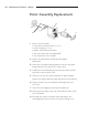
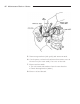
Rotor Assembly Replacement
1. Remove and set aside:
• two motor housing scr
ews
(not shown)
• motor housing (not shown)
• plastic fan A (discard old fan)
• two coil screws and lock washers
B
• coil (keep wires connected) D
2.
Remove and discard the rotor E and two plastic
brackets C.
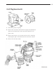
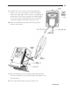
3. Press the new plastic bearing bracket onto the threaded
brass inserts in the front of the motor case.
4. Install new r
otor assembly by inserting the shaft (helical
gear side) onto the gear case.
5. Place the coil ov
er the rotor and keep the copper-shaded
poles on the right-hand side (same side as the on/off switch).
6. Snap into place the second plastic bearing bracket on
the rotor.
7. Insert two self-tapping screws (w/lock washers).
8. Starting at an angle, pr
ess fan (with hub side down) onto
the rotor shaft.
9. Reinstall two motor housing screws and tighten the
self-tapping screws to secure the motor housing cover.
A
B
C
D
E
C