
Manual

2
PERFORMANCE INDICATORS
OPTIONAL SMARTAP® WATER QUALITY MONITOR
WaterGroup’s12403SeriesReverseOsmosisSystemsincorporateaprovenperformanceindicator.OurpatentedSmartap
®
WaterQuality
MonitorusesdualprobeLOGICPULSEMEMORYtechnologytoaccuratelyindicatemembraneperformance.Asplit-secondpowerpulse
compares feed water Total Dissolved Solids (TDS) level with that of the product water. Then, by reversing the polarity of the electronic pulse,
the probes are cleaned and kept free of chemical plating. A nine-volt alkaline battery provides power to the Monitor. For optimum monitor
performance, the battery should be replaced each time system is sanitized.
NOTE: Monitor Troubleshooting Indicators and Common Solutions are shown in Table 5 on Page 12.
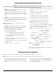
Push Button Actuated Smartap® – 12403 Series
Pressing a test button located on the manifold cover activates monitor. When button is pressed, and momentarily held down, monitor
reports membrane status by illuminating a light located next to test button. A green light means system is operating normally. A yellow light
indicates system needs servicing (membrane may be depleted or fouled). While the button may be pressed at any time, the most accu-
rate readings are obtained when the system is making water for at least 10 minutes.
The customer can also contact the local dealer for water sampling service or kit.
INTER-COMPONENT CONNECTIONS
Connections between cold water supply line, RO Module, storage tank, product water faucet, and drain line are accomplished using plas-
tictubingandpush-togetherquick-connecttypettings.
PLASTIC TUBING
1. Cuttubeendssquareandstraight.Donotdeformtube(i.e.,
cause tube to compress its diameter so it is no longer round).
2. Make sure outer surface of tube is clear of marks or scratches for
alengthequaltotwicetubediameter.Thisallows“O”ringto
seat properly against tube.
3. Avoid sharp changes in direction when routing tubing. Sharp
turns cause tubing to flex and deform, which reduces its flow
capacityandmayincreaselateralstressonthettings,causing
leakage.
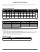
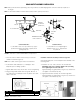
QUICK-CONNECT FITTINGS
Fittings consist of two parts: a Body and a colored collet and sym-
bol. Collet color and symbol corresponds to tubing to be used at
that connection (Figure 2.A.).
1. Toinstallatube,pushitthroughColletuntilitseatsrmlyatbot-
tomoftting(Figure2.Aand2.B.).
2. To remove a tube, push and hold Collet against Body while pull-
ing tube out (Figure 2.C.).
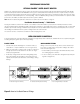
Figure 2: How to Use Quick-Connect Fittings
A. Push tube through Collet into Body.
COLLET
BODY
B. Tube must seat firmly at bottom of fitting. C. Push Collet against Body to release tube.