
Manual

1
INSTALLATION REQUIREMENTS
READ THIS ENTIRE INSTALLATION AND SERVICE GUIDE BEFORE BEGINNING INSTALLATION
The 12403 Series Reverse Osmosis (RO) Drinking Water Treatment Systems have been designed for ease of installation and serviceability
andareconstructedwiththenestmaterialsavailable.Usingtheseinstructionsandpayingcloseattentiontotheparametersoutlined
within “CONDITIONS FOR USE” detailed on Page II will ensure a successful installation.
All systems must be installed in accordance with applicable city, state, provincial and local plumbing codes. For installation in Massa-
chusetts, the Massachusetts Plumbing Code 248 CMR shall be adhered to. Consult your licensed plumber for installation of this system.
The use of saddle (piercing) valves is not permitted. To ensure a system continues to operate at its optimum level, it is necessary to
havearoutinemaintenanceandreplacementschedule(Table4).Frequencyatwhichltersmustbechangedwilldependonquality
of feed water supply and level of system usage.
These RO systems contain a replaceable treatment component critical to the efficiency of the system.
Replacement of the reverse osmosis component should be with one of identical specification, as defined by WaterGroup to assure the
same efficiency. Product water shall be tested periodically to verify the system is performing properly. Operator performs test using
the optional Smartap
®
Water Quality Monitor.
All state, provincial and local government codes regarding installation of these devices must be observed.
PREPARATION
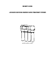
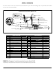
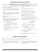
1. Check that all appropriate components are packed with your
system (Figures 1.A. and 1.B.).
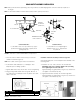
2.DeterminelocationsforROcomponentinstallation.Tworequire-
ments for consideration are: access to cold water supply line and
householdsinkdrainpipe.Specicrequirementsaredetailedin
Table 3.
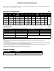
COMPONENT LOCATION REQUIREMENTS Table 3
PRODUCT WATER FAUCET REVERSE OSMOSIS MODULE
Faucet may be installed in any convenient location.
Make sure underside of location is free of obstructions.
Module may be installed under sink or in any convenient location within 15 feet of source
water supply and faucet.
STORAGE TANK
Tank may be placed in any space within 15 feet of faucet, generally under kitchen sink or in an adjacent unused cabinet.
Tubing length between components should be kept to a minimum, avoiding sharp bends or kinks.
DO NOT PLACE MODULE WHERE IT WILL BE EXPOSED TO FREEZING AND/OR DIRECT SUNLIGHT.
MODULE MUST BE EASILY REMOVABLE FOR PERFORMANCE OF ROUTINE MAINTENANCE.
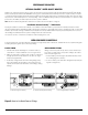
Mount Module on side of cabinet using bracket (attached to Module) and two screws provided in the Installation Kit.
HOLD THE MODULE BY THE FILTER HOUSINGS WHEN PICKING UP OR CARRYING UNIT.
NOTE
THISDRINKINGWATERSYSTEMISFORUSEONPOTABLEWATERSUPPLIESONLY.
SOURCEWATEREXCEEDINGCHEMICALPARAMETERSREQUIRESPRE-TREATMENT.
CAUTION
DO NOT USE WITH WATER THAT IS MICROBIOLOGICALLY UNSAFE OR OF UNKNOWN QUALITY
WITHOUT ADEQUATE DISINFECTION BEFORE OR AFTER THE SYSTEM.
MAINTENANCE REQUIREMENTS Table 4
SERVICE REQUIREMENTS RECOMMENDED SERVICE INTERVALS
To insure the system operates at its optimum level, certain routine maintenance must be
performed. Frequency of maintenance performance will depend on feed water quality and
level of system usage.
CLEAN: Each time filters are replaced
SANITIZE: At least once a year and each time membrane is replaced
Replace filters as required or every 6 to 12 months depending on feed water quality.
Replace membrane as required based on Smartap®
Water Quality Monitor indication or periodic TDS rejection tests.
Maximum recommended service life for membrane is 60 months.