
Manual


6
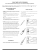
METAL PRODUCT WATER FAUCET INSTALLATION AND SYSTEM CONNECTIONS
Install faucet on flat surface at least 2” in diameter. Unused 1 1/4” hole is ideal.
Steps unique to a specific configuration are so noted. All other steps are common to either configuration.
New Faucet Installation
Refer to Faucet Site Preparation, Page 5.
Replacement Faucet Installation
Verifysizeofexistingholeis11/4”.
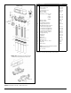
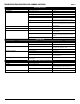
NOTE: ItemcalloutsrefertoFigure7unlessnotedotherwise.
1. Air Gap Only: Verify faucet body, metal base washer, and rub-
ber base washer are in place above sink (Items 1, 3, and 2).
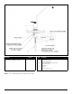
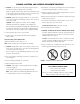
2. CAUTION:FlowRestrictor(FLR)isinstalledinsidethe1/4”redtub-
ing on the end with the label. DO NOT TRIM
THEENDOFTHE1/4”FLRREDTUBINGTHAT
INCLUDESTHELABEL(SeeFigure8).
Air Gap Only:Install3/8”redtubingfromInstallationKitonto
largerhosebarbasshowninFigure7.
3. Air Gap Only:Connectthe1/4”FLRredtubingend
with FLR label between the module red collet near
symbol shown and the faucet:
a. Air Gap Only:Insertthe3/8”redtubeintothemountinghole.
b. Air Gap Only: Insertthe1/4”FLRredtubing
upwards through mounting hole.
c. Air Gap Only: Position module in desired location. Trim the
end of FLR tubing without label to desired length. Attach FLR
tubingontosmallerhosebarbasshowninFigure7.
4. Lower faucet into mounting hole and place faucet over hole.
5. Air Gap Only: Install slotted washer, spacer, faucet washer, and
nut onto faucet nipple below sink and snug them up (Items 4, 5,
6,and7).Besuretoproperlyalignfaucetbeforetightening.Do
not over tighten.
6. Installfaucetconnector(Item8),packagedwithfaucet,onto
faucetnipple.Install3/8”bluetubeintofaucetconnector.
7. Trim3/8”bluetubetodesiredlength.Install3/8”blue
tubeinto3/8”bluecolletlocatedonsideofmodule
near symbol as shown.
8. CAUTION:Red3/8”tubeconnectingproductwater
faucet to drain saddle must run vertically (or as closely as pos-
sible) with no sharp bends or loops (See Figure 4).
Connect loose ends of tubing as follows:
Air Gap Only: Connect3/8”redtubingto3/8”ondrainsaddle
using compression nut.
Refer to steps 2-4 in Polymer Tank Assembly for use of compres-
sion nuts.
Storage Tank Connection - Polymer Tank Assembly
NOTE: The following Instructions refer to Page IV, Figure 1.B., Item 1.
1. Hand-tighten the ball valve onto the RO storage tank.
CAUTION: Do not over tighten ball valve as this may strip threads
or compromise the “O” ring seal.
2. Slidecompressionnutover3/8”whitetubing.
3. Push3/8”whitetubingintotheballvalveasfaraspossible.
4. Whileholding3/8”whitetubingintheballvalve,hand-tighten
the compression nut onto the ball valve.
5. The basic installation is complete and system is ready for activa-
tion (See Page 10).
6. Connect3/8”whitetubingtothewhitecolletonthe
module.
Storage Tank Connection - Metal Tank Assembly
NOTE: The following instructions refer to Page IV,
Figure 1.B, Items 2 & 3.
NOTE: Refer to Page 2, Inter-Component Connections for
instructions on how to install tubing.
1. Install ball valve (located inside of master pack box) onto the
1/4”storagetanknipple.Usethreadsealingtapetosealthreads
between ball valve and nipple.
2. Connect3/8”whitetubingbetweenmodule
(near symbol as shown) and storage tank
shut-off valve.
3. The basic installation is complete and system is ready for
activation (see Page 10).
NOTE: With the storage tank empty, ensure the air-cell pre-charge
is set to manufacturers instructions marked on tank. Use a hand
power air pump to top up if necessary.
WARNING:Neveruseanaircompressortollaircellofareverse
osmosis system storage tank.
NOTE: Optional stem elbows have been supplied to allow
installations with limited space to be simpler. Connect the
stem elbow into the inlet, faucet, tank and drain parts as
requiredbeforeconnectingtubing.