
Manual

4
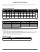
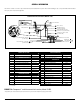
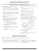
FIGURE 4:DrainHoleLocationandInstallation,AirGapFaucet
1. Select a location for drain hole based on type of sink and
orientation of drain line (Figure 4).
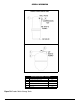
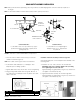
NOTE: Item callouts refer to Figure 5 unless noted otherwise.
2. Position drain outlet saddle (Item 1) on drainpipe. Allow
adequatespacefordrillingoperation.
3. Tighten saddle bolts evenly on both sides. Avoid over-tightening.
4. Usingopeningindrainsaddleoutletasaguide,drilla3/8”to
7/16”diameterholeindrainpipe.Cleananydebrisoutofdrain
saddle connection.
ITEM DESCRIPTION PART NO.
1 Drain Saddle, Air Gap, 3/8” Connection 92160
FIGURE 5: Drain Outlet Assembly
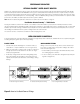
Installation of Ball Valve Assembly on Plastic Storage Tank
Theballvalveandquickconnectadaptermustbeinstalledonthe
RO storage tank.
a. Installthe1/4”x3/8”maleconnectorontotheballvalve.
IMPORTANT– Make sure to install the ‘INSERT’ in the 3/8” tubing
before tightening the nut of the ball valve.
Tightenthettingverygentlyuntilitissnug.Beverycarefulnotto
over-tighten or the threads may strip.
b. Tighten the ball valve assembly onto the RO storage tank.
Tightenthettingverygentlyuntilitissnug.Be very careful not to
over-tighten or the threads may strip.
DRAIN OUTLET ASSEMBLY INSTALLATION
NOTE:State,provincialandlocalplumbingcodesmayprohibituseofsaddle-tappingdrainconnectionsandmayrequireuseof
an air gap.
NOTE: Location and orientation of drain outlet assembly is vital to system performance.
Horizontal Drain Line:
Locate drain hole as close as possible to top of pipe
(between 45º and top) and as far as practical from
garbage disposal.
Vertical Drain Line:
Locate drain hole on a straight length of
drainpipenextto“P”/”S”trapbetween
trap and sink.
INSTALL HERE
DO NOT INSTALL HERE
MAXIMUM DISPLACEMENT
FROM TOP CENTER - 45°
DISPOSAL
SINK SINK
DRAIN LINE
FROM AIR GAP
(AIR GAP ONLY)
VERTICAL
MOUNT
HORIZONTAL
MOUNT
1
DRAINPIPE
ADAPTER
INSERT
BALL VALVE
3/8”
TUBING
TANK