OWNER’S GUIDE ADVANCED REVERSE OSMOSIS WATER TREATMENT SYSTEMS Model Series 12403
Please fill in the following information and retain for reference: Unit Model Number:___________________________________________________________________ Serial Number: ________________________________________________________________________ Date Purchased: ______________________________________________________________________ Date Installed:_________________________________________________________________________
INTRODUCTION Congratulations, on the purchase of your new Advanced Reverse Osmosis Water Treatment System. Treated with care and regular maintenance, your new system will provide many years of service delivering great tasting water to the tap. By now, you have probably already opened the box to survey the contents. Please take a few moments to review this manual before proceeding with the installation and use of the system.
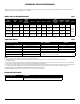
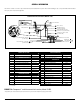
CONTAMINANT REDUCTION PERFORMANCE Hydrotech Performance as tested by an outside agency is shown below. Past test results may not be indicative of current performance and your results may vary depending on conditions. MODELS AND SYSTEM CONFIGURATIONS Table 1 Model Description Storage Tank # of Vessels Storage Tank Capacity Litres (gal) Vessel 4 Daily Production Rate2 L/day (G/day) Vessel 1 Vessel 2 Vessel 3 Efficiency Rating3 % Recovery Rating4 % 4VTFC09G-PB Plastic/Metal 4 6.81 (1.
GENERAL INFORMATION This Owner’s Guide covers all components that may be included with a system. Information relating to any component that is NOT included with your system may be disregarded.
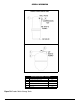
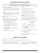
GENERAL INFORMATION Product water Storage tanks PRODUCT WATER STORAGE TANKS - ALL SYSTEMS Item Description Part No. 1 Storage Tank Assembly, Polymer 2 Storage Tank Assembly, Metal 3 Ball Valve, 3/8”, Steel Tank 4 92313 92342/92294 33503601 Ball Valve, 3/8”, Plastic Tank 80704 Insert, 3/8” 92329 Figure 1.
INSTALLATION REQUIREMENTS READ THIS ENTIRE INSTALLATION AND SERVICE GUIDE BEFORE BEGINNING INSTALLATION The 12403 Series Reverse Osmosis (RO) Drinking Water Treatment Systems have been designed for ease of installation and serviceability and are constructed with the finest materials available. Using these instructions and paying close attention to the parameters outlined within “CONDITIONS FOR USE” detailed on Page II will ensure a successful installation.
PERFORMANCE INDICATORS OPTIONAL SMARTAP® WATER QUALITY MONITOR WaterGroup’s 12403 Series Reverse Osmosis Systems incorporate a proven performance indicator. Our patented Smartap® Water Quality Monitor uses dual probe LOGIC PULSE MEMORY technology to accurately indicate membrane performance. A split-second power pulse compares feed water Total Dissolved Solids (TDS) level with that of the product water.
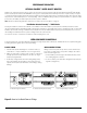
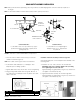
SADDLE-TAPPING VALVE INSTALLATION ON COPPER TUBE CAUTION: This saddle-tapping valve is not designed for installation on flex line tubing. NOTE: For installation in Massachusetts, the Massachusetts Plumbing Code 248 CMR shall be adhered to. Consult your licensed plumber for installation of this system. The use of saddle (piercing) valves is not permitted. 1. CAUTION: If no shut off valve is installed under sink, close main water valve during this Installation. 4.
DRAIN OUTLET ASSEMBLY INSTALLATION NOTE: State, provincial and local plumbing codes may prohibit use of saddle-tapping drain connections and may require use of an air gap. NOTE: Location and orientation of drain outlet assembly is vital to system performance.
PRODUCT WATER FAUCET SITE PREPARATION Refer to Faucet Installation Instructions (Page 6) for site location and mounting hole specifications. Primary considerations for site selection are convenience of use and an open area under sink. An existing 7/8” Sink Hole will also accommodate metal faucets with air-gap connections. Always check underside of selected location for obstructions. NOTE: Location and orientation of drain outlet assembly is vital to system performance.
METAL PRODUCT WATER FAUCET INSTALLATION AND SYSTEM CONNECTIONS Install faucet on flat surface at least 2” in diameter. Unused 1 1/4” hole is ideal. Steps unique to a specific configuration are so noted. All other steps are common to either configuration. New Faucet Installation Refer to Faucet Site Preparation, Page 5. Connect loose ends of tubing as follows: Air Gap Only: Connect 3/8” red tubing to 3/8” on drain saddle using compression nut.
Description Chrome Plated Metal Air Gap Faucet (USEPA Compliant, not available in California) Part No.
Model 12403 Item Description Part No.
ACTIVATING THE SYSTEM CAUTION: Make sure all water supply lines, drain lines, and fittings are secure and free from leakage. 1. Open source water supply valve. Close product water faucet. Check for leakage. 7. T est battery connection by activating monitor. Press push button. If either indicator light illuminates, connection is good. 2. T urn tank valve one-quarter turn counter- clockwise to open valve (handle should be in line with tubing as it enters connection).
CLEANING, SANITIZING, AND CARTRIDGE REPLACEMENT PROCEDURE lean filter housings and manifold ports, inside and outside, with C washcloth and cleaning solution. Do not use abrasive materials. 1. Mix mild cleaning solution of dish soap and clean potable water in plastic bowl. 9. Rinse manifold/housings with clean potable water. 2. Empty storage tank and relieve system pressure. Verify tank valve is open. Close feed water supply valve and open product water faucet. 10.
CLEANING, SANITIZING, AND CARTRIDGE REPLACEMENT PROCEDURE 19. CAUTION: Do not remove protective plastic bag from replacement filter/membrane cartridges until so instructed. 28. Test battery connection by activating monitor. Press push button. If an indicator light illuminates, connection is good. I nstall “O” rings into filter housings. Open top of filter bag enough to expose filter cap and “O” ring grooves. Place a small amount of “O” ring lubricant on surface of each “O” ring. 29.
TROUBLESHOOTING INDICATORS AND COMMON SOLUTIONS Table 5 WATER VOLUME AND QUALITY Symptom Condition Action No product water. Water supply is turned OFF. Turn water ON. Not enough product water. Low water pressure. Check source water line pressure. Water supply is blocked. Clear restriction. Storage tank valve is closed. Open storage tank valve. Storage tank is depleted. Increase product water storage capacity and/or install membrane and flow restrictor with higher output rating.
13
LIMITED WARRANTY Subject to the conditions and limitations described below, WaterGroup warrants its Model 12403 Series Reverse Osmosis Drinking Water Treatment Systems (excluding membrane, cartridge filters and battery), when installed in accordance with WaterGroup specifications, to be free from defects in materials and workmanship under normal use within the operating specifications for a period of two (2) years from the date of purchase (with bill of sale) or 2.