
Instruction Manual

I
INTRODUCTION
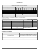
MODEL NUMBERS AND SYSTEM CONFIGURATIONS Table 1
GUIDE IS APPLICABLE TO THE REVERSE OSMOSIS DRINKING WATER TREATMENT SYSTEMS AS SPECIFIED IN THIS TABLE
Select System Code and Output Code to Determine Model Number
System Code 12301 12302 12303
Output (GPD)* 9 25 50 75 9 25 50 75 9 25 50 75
Output Code 03 02 01 00 00 01 02 03 00 01 02 03
Vessels 3 4 4
Monitor None None Push Button Smartap
®
Sediment Filter None String Wound Polypropylene String Wound Polypropylene
Pre-Filter Dual-Purpose Activated Carbon Activated Carbon
Membrane Thin Film Composite
Post Filter Activated Carbon
* Manufacturer’s Specification with inlet conditions of 345 kPa (50 psig), 25° C (77° F), going to atmosphere.
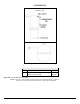
CONDITIONS FOR USE
THIN FILM COMPOSITE MEMBRANE
Source Water Supply Profile Chemical Parameters Max mg/L
Community/Private Chlorinated/Non-Chlorinated Hardness (CaCO
3
) <350 (20 gpg)
Feed Water Pressure
1
242-690 kPa (35-100 psig) Iron (Fe ) <0.1
Temperature 4°-38° C (40°-100° F) Manganese (Mn) <0.05
pH Range 3.0 - 11.0 Hydrogen Sulfide (H
2
S ) 0.00
Maximum TDS Level 2000 mg/L Residual Chlorine (Cl
2
) <2.0
Turbidity** <1.0 NTU
Maximum SDI***
<4.0
** Nephelometric Turbidity Unit
*** Silt Density Index: Value stated in SDI units.
NOTE: 1. PRESSURE REGULATOR IS RECOMMENDED FOR FEED WATER PRESSURES EXCEEDING 552 kPa (80 psig).
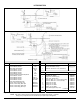
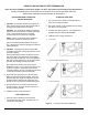
OPTIONS AND ACCESSORIES
PRODUCT WATER FAUCETS BOOSTER PUMP
Faucets are available as Air Gap and Non-Air Gap in
Chrome-Plated Metal (EPA and California Proposition 65 Compliant)
or an Air Gap molded Polymer.
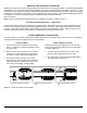
A booster pump may be used if system pressure is below 242 kPa (35 psi).
Pump should be placed near RO Module and installed in feed water line just
before it enters Module. Power supplies are available in a variety of voltages.
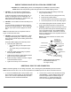
PUSH BUTTON SMARTAP
®
WATER QUALITY MONITOR
Indicator lights located on the module cover report system status.
Pressing a test button located on the manifold cover activates monitor.