OWNER’S GUIDE ADVANCED REVERSE OSMOSIS WATER TREATMENT SYSTEMS MODEL SERIES 12301 MODEL SERIES 12302 MODEL SERIES 12303
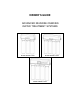
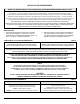
INTRODUCTION MODEL NUMBERS AND SYSTEM CONFIGURATIONS Table 1 GUIDE IS APPLICABLE TO THE REVERSE OSMOSIS DRINKING WATER TREATMENT SYSTEMS AS SPECIFIED IN THIS TABLE Select System Code and Output Code to Determine Model Number System Code 12301 12302 12303 Output (GPD)* 9 25 50 75 9 25 50 75 9 25 50 75 Output Code 03 02 01 00 00 01 02 03 00 01 02 03 Vessels 3 4 4 Monitor None None Push Button Smartap Sediment Filter None String Wound Polypropylene String Wound Polypr
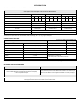
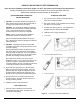
INTRODUCTION SYSTEMS WITH NON-AIR GAP FAUCET (MODEL 12301 SHOWN) SYSTEMS WITH AIR GAP FAUCET, MODELS 12302 AND 12303 (MODEL 12303 SHOWN) REVERSE OSMOSIS SYSTEM Item 1 2 Description Without Water Quality Monitor 3 Vessel Module, 50 GPD Without Water Quality Monitor 4 Vessel Module, 15 GPD 4 Vessel Module, 25 GPD 4 Vessel Module, 50 GPD 4 Vessel Module, 75 GPD ® Push Button Smartap Water Quality Monitor 4 Vessel Module, 15 GPD 4 Vessel Module, 25 GPD 4 Vessel Module, 50 GPD 4 Vessel Module, 75 GPD Reverse
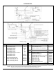
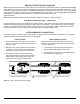
INTRODUCTION PRODUCT WATER STORAGE TANKS PRODUCT WATER STORAGE TANKS - ALL SYSTEMS Item 1 2 Description Storage Tank Assembly, Polymer Storage Tank Assembly, Metal Part No. 34500023 42600029 Figure 1B: Product Water Storage Tanks. NOTE: This Owner’s Guide covers all components that may be included with a system. Information relating to any component that is not included with your system may be disregarded.
INSTALLATION REQUIREMENTS READ THIS ENTIRE INSTALLATION AND SERVICE GUIDE BEFORE BEGINNING INSTALLATION The 123 Series Reverse Osmosis (RO) Drinking Water Treatment Systems have been designed for ease of installation and serviceability. They are constructed with the finest materials available. Using these instructions and paying close attention to parameters outlined within "CONDITIONS FOR USE" detailed on Page I will ensure a successful installation.
SMARTAP® WATER QUALITY MONITOR ® WaterGroup’s 12303 Series Reverse Osmosis Systems incorporate a proven performance indicator. Our patented Smartap Water Quality Monitor uses dual probe LOGIC PULSE MEMORY technology to accurately indicate membrane performance. A splitsecond power pulse compares feed water Total Dissolved Solids (TDS) level with that of the product water. Then, by reversing the polarity of the electronic pulse, the probes are cleaned and kept free of chemical plating.
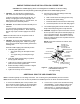
SADDLE-TAPPING VALVE INSTALLATION ON COPPER TUBE CAUTION: This saddle-tapping valve is not designed for installation on flex line tubing. NOTE: State and local plumbing codes may prohibit use of saddle-tapping valves. 1. 4. Connect source water feed tubing to valve body using compression fitting. CAUTION: If no shut off valve is installed under sink, close main water valve during this Installation. a. Slide nut and sleeve onto tubing (in that order). Locate shut off valves on water lines under sink.
DRAIN OUTLET ASSEMBLY INSTALLATION NOTE: State and local plumbing codes may prohibit use of saddle-tapping drain connections and may require use of an air gap. NOTE: Location and orientation of drain outlet assembly is vital to system performance.
PRODUCT WATER FAUCET SITE PREPARATION Refer to Faucet Installation Instructions (Pages 6 or 8) for site location and mounting hole specifications. Primary considerations for site selection are convenience of use and an open area under sink. Always check underside of selected location for obstructions. STAINLESS STEEL SINK PORCELAIN/ENAMEL OVER STEEL OR CAST IRON SINKS 1. 1. Use a center punch to make a small indentation to mark center of desired location.
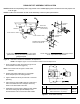
METAL PRODUCT WATER FAUCET INSTALLATION AND SYSTEM CONNECTIONS Install faucet on flat surface at least 2" in diameter. Unused 1 1/4" hole is ideal. Steps unique to a specific configuration are so noted. All other steps are common to either configuration. New Faucet Installation 8. Refer to Faucet Site Preparation, Page 5. Replacement Faucet Installation Verify size of existing hole is 1 1/4". Connect loose ends of tubing as follows: a.
1 9 NON AIR GAP 4A 3 2 SINK OR COUNTER MATERIAL NON AIR GAP 4 5 AIR GAP AIR GAP ONLY 6 7 DRAIN LINE FROM AIR GAP TO DRAIN (3/8" RED TUBING) DRAIN LINE TO AIR GAP (1/4" RED TUBING) Description Chrome Plated Metal Non-Air Gap Faucet (Faucet not available in California) Chrome Plated Metal Non-Air Gap Faucet (EPA and California Proposition 65 Compliant) Chrome Plated Metal Air Gap Faucet (Faucet not available in California) Chrome Plated Metal Air Gap Faucet) (EPA and California Proposition 65 Compli
POLYMER PRODUCT WATER FAUCET INSTALLATION AND SYSTEM CONNECTIONS Install on flat surface at least 2 7/16" in diameter. Unused 1 1/4"- 1 7/16" opening is ideal. d. Trim 1/4” red tubing coming from faucet to desired length and connect to ¼” union connector. New Faucet Installation Refer to Faucet Site Preparation, Page 5. 5. Align faucet in mounting hole: Replacement Faucet Installation Plain Front: Align body with narrow face forward. Verify size of existing hole.
Item Description Part No. Item Description Part No.
MODEL 12301 Item 1 1A 2 3 4 5 6 7 8 9 10 11 12 FLOW RESTRICTOR LABEL 12A 13 14 15 16 17 18 19* 19A* 20 21 22 23 23A 24 25 26 26A 27 28 29 30 31 32* Description Cover, 3-vessel Manifold Cover, 4-vessel Manifold Bracket, Mounting Screw, Mounting Bracket Screw, inlet Valve Cover Cover, Inlet Valve "O" Ring, Inlet Valve Cover Shut Off Assembly Tubing, 1/4” x 48” White Elbow, 1/4" Stem w/white collet Cap, Flow Control w/”O” Ring Elbow, 1/4" Stem w/red collet Flow Restrictor, Model 12301 Series 50 GPD Flow
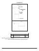
MODEL 12302 Model 12303 ® Push Button Smartap Monitor Module Cover and Monitor Connections FLOW RESTRICTOR LABEL Figure 10.
ACTIVATING THE SYSTEM CAUTION: Make sure all water supply lines, drain lines, and fittings are secure and free from leakage. NOTE: Item callouts refer to Page 10, Figure 10.A, and Page 11, Figure 10.B. 6. Replace manifold cover and tighten screws. 7. Test battery connection by activating monitor. Press push button. If either indicator light illuminates, connection is good. NOTE: Release button or close faucet immediately after light illuminates. Test is to confirm battery connection, not water quality.
CLEANING, SANITIZING, AND CARTRIDGE REPLACEMENT PROCEDURE 1. Mix mild cleaning solution of dish soap and clean potable water in plastic bowl. 9. Rinse manifold/housings with clean potable water. 2. Empty storage tank and relieve system pressure. Verify tank valve is open. Close feed water supply valve and open product water faucet. 10. Inspect manifold and filter housing "O" ring groove area for damage (i.e., nicks or scratches). Replace damaged components.
CLEANING, SANITIZING, AND CARTRIDGE REPLACEMENT PROCEDURE 28. Test battery connection by activating monitor. Press push button. If an indicator light illuminates, connection is good. 19. CAUTION: Do not remove protective plastic bag from replacement filter/membrane cartridges until so instructed. Install "O" rings into filter housings. Open top of filter bag enough to expose filter cap and "O" ring grooves. Place a small amount of "O" ring lubricant on surface of each "O" ring.
TROUBLESHOOTING INDICATORS AND COMMON SOLUTIONS Table 4 WATER VOLUME AND QUALITY Symptom Condition Action No product water. Water supply is turned OFF. Turn water ON. Not enough product water. Low water pressure. Water supply is blocked. Storage tank valve is closed. Storage tank is depleted. Check source water line pressure. Clear restriction. Open storage tank valve. Increase product water storage capacity and/or install membrane and flow control with higher output rating.
LIMITED WARRANTY Subject to the conditions and limitations described below, WaterGroup warrants its Model 12301, 12302, and 12303 Series Reverse Osmosis Drinking Water Treatment Systems (excluding cartridge filters and battery), when installed in accordance with WaterGroup specifications, to be free from defects in materials and workmanship under normal use within the operating ® specifications for a period of two (2) years from the date of purchase.