
Install Instructions


MODEL CGT450 (for boilers with tankless coil)
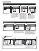
HOW TO WIRE
Connect input voltage (120 VAC,
60 HZ) to terminals 1 and 2.
Connect input voltage (120 VAC, 60 HZ) to ter-
minals 1 and 2.
Optional water feeder connection. Connect feeder
N to terminal 2. Connect Feeder H to terminal 1.
Connect feeder “FEED” or “W” to terminal A. For
water feeders with 2 leads, connect feeder neutral
to terminal 2 and feeder hot to terminal A.
Note: Use of a solenoid valve or McDonnell &
Miller Model 101A water feeder may cause flood-
ing and is not recommended for use with this
low water cut-off.
BURNER
POWER
SOURCE
120VAC
AP2P112
FACTORY
INSTALLED
JUMPER.
DO NOT
REMOVE
BURNER
NEUTRAL
HOT
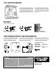
MODEL CG450
Connect terminal 2 to burner circuit
neutral. Connect terminal P2 to
burner Circuit in series with other
limit controls. Consult boiler manu-
facturer instructions for proper ter-
minal connections. Control should
be wired in series with and before
other limit controls.
Connect terminal 2 to burner circuit neutral.
Connect terminal P2 to burner Circuit in series
with other limit controls. Consult boiler manu-
facturer instructions for proper terminal connec-
tions. Control should be wired in series with and
before other limit controls.
Connect “LOW LIMIT” terminals on CycleGard
control to the terminals on the tankless aquas-
tat.
Connect”THERMOSTAT” terminals on
CycleGard control to T-T terminals on burner
primary control.
Optional water feeder connection.
Connect feeder N to terminal 2.
Connect Feeder H to terminal 1.
Connect feeder “FEED” or “W” to
terminal A. For water feeders with
2 leads, connect feeder neutral
to terminal 2 and feeder hot to ter-
minal A. Note: Use of a solenoid
valve or McDonnell & Miller Model
101A water feeder may cause
flooding and is not recommended
for use with this low water cut-off.
Connect “BURNER” terminal on the
CycleGard control to the orange
burner wire (120VAC) located
under the oil burner transformer.
See opposite page for schematic
wiring diagram and additional
SmartCycle description.
1
BURNER
POWER
SOURCE
120VAC
2
FACTORY
INSTALLED
JUMPER.
DO NOT
REMOVE
AP2P11 BURNER LOW LIMIT THERMOSTAT
NEUTRAL
HOT
1
AP2P11 BURNER LOW LIMIT THERMOSTAT
BURNER
POWER
SOURCE
120VAC
+
0
LIMIT
CONTROLS
2
HOTNEUTRAL
BURNER
CIRCUIT
2
AP2P11 BURNER LOW LIMIT THERMOSTAT
BURNER
POWER
SOURCE
120VAC
+
0
LIMIT
CONTROLS
2
BURNER
CIRCUIT
WATER
FEEDER
3
AP2P11 BURNER LOW LIMIT THERMOSTAT
BURNER
POWER
SOURCE
120VAC
+
0
LIMIT
CONTROLS
2
BURNER
CIRCUIT
TANKLESS
AQUASTAT
WATER
FEEDER
NEUTRAL
HOT
4
BURNER
POWER
SOURCE
120VAC
+
0
LIMIT
CONTROLS
2
BURNER
CIRCUIT
TANKLESS
AQUASTAT
PRIMARY
BURNER
CONTROL
TT
AP2P11 BURNER LOW LIMIT THERMOSTAT
WATER
FEEDER
5
AP2P11 BURNER LOW LIMIT THERMOSTAT
BURNER
POWER
SOURCE
120VAC
+
0
LIMIT
CONTROLS
2
BURNER
CIRCUIT
TANKLESS
AQUASTAT
PRIMARY
BURNER
CONTROL
TT
WATER
FEEDER
6
BURNER
POWER
SOURCE
120VAC
+
0
LIMIT
CONTROLS
AP2P112
HOTNEUTRAL
BURNER
CIRCUIT
BURNER
2
BURNER
POWER
SOURCE
120
VAC
+
0
LIMIT
CONTROLS
AP2P112
GAS
VALVE*
BURNER
GAS
VALVE*
C
H
WATER
FEEDER
3
BURNER
POWER
SOURCE
120
VAC
+
0
LIMIT
CONTROLS
AP2P112
BURNER
GAS
VALVE*
H
C
WATER
FEEDER
4
OPTIONAL
ACTIVATION
Connect “BURNER” terminal on the CycleGard
control to the orange burner wire (120VAC)
located under the oil burner transformer. See
opposite page for schematic wiring diagram
and additional SmartCycle description.
OPTIONAL ACTIVATION