
User Manual

www.hydrofarm.com
2
INSTRUCTION MANUAL
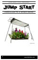
MODULAR T5 4 STRIP DOCK
Thank you for purchasing the Modular T5 4 Strip Dock. This easy-to-use T5 xture combines up to four T5 Light Strips to create a powerful stand-alone grow xture. Start small and
add on as your garden grows.
READ AND SAVE THESE INSTRUCTIONS
ASSEMBLING FIXTURE USING THE MODULAR T5 4 STRIP DOCK
1. Snap one strip into one dock. Match the U-shape of the strip with the U-shape grooves on the docking plate. The strip should be silver side
face-up, bulb side face-down. Aach the other dock to the other side of the strip.
2. Aach the other strips where applicable. When adding more than a single strip, each strip should be posioned in an alternate male-
to-female fashion. Check the docking plate to see whether the rst strip is aached to the male or female receptacle through the hole
on the docking plate. The reector that goes next to the rst should be ipped so its receptacle faces the opposite direcon through the hole
in the docking plate. The holes in the end piece will guide you.
3. Insert a third Link Cord to the other two openings on the rst docking plate. The result will be two Link Cords forming two loops on one side
and one Link Cord forming one loop on the other side. Using the Link Cords allows you to power all four bulbs with a single power. This is oponal.
4. Insert the power cord into the next available receptacle.
5. You can link daisy-chain two 2 systems with the oponal Link Cord (JSFL). The 4 system cannot be daisy-chained.
HANGING THE MODULAR T5 LIGHT SYSTEM
1. Locate two ceiling joists with a stud nder.
2. Screw an eyebolt or some other means of hanging the reector securely from the ceiling in to the rst joist. Screw a second eyehook into the other joist
to balance hanging the reector.
3. Aach a chain, rope or other sturdy material to the eyehooks.
4. Li the T5 by the metal handle hangers and ease it onto the hanging mechanism. Adjust height if necessary. DO NOT li the T5 using the power cords.
USING THE MODULAR T5 LIGHT SYSTEM AS STAND-ALONE UNIT
1. Insert the four legs into each slot on the two docking plates with the rubber feet pointed down. Push and twist the legs all the way in - failure to insert
the legs enrely may result in the system wobbling.
CARE AND CLEANING
1. Unplug the T5 and allow to cool.
2. Unscrew the bulbs and set aside.
3. Mix warm water and mild soap and apply sparingly to the strips and reectors with a clean washcloth. Dry system with a second washcloth.
4. Run a dry, so washcloth over bulbs to remove dust parcles.
5. Screw bulbs back into the reectors.
6. Plug in the power cords.
7. DO NOT immerse the system in water.
8. DO NOT use gasoline, paint thinner or other chemicals to clean the system.
CONECTOR MODULAR DE 4 BARRAS T5
Gracias por comprar el conector modular de 4 barras T5. Este accesorio fácil de usar combina hasta 4 barras de iluminación T5 para crear un accesorio de culvo independiente y
potente. Empiece poco a poco y vaya añadiendo barras a medida que crezca su plantación.
LEA Y CONSERVE ESTAS INSTRUCCIONES
MONTAJE DEL ACCESORIO MEDIANTE EL CONECTOR MODULAR DE 4 BARRAS T5
1. Acople una barra por conector. Haga coincidir la forma en U de la barra con los surcos con forma en U de la placa de conexión. La barra debe tener la parte
plateada hacia arriba y la parte de la bombilla hacia abajo. Acople el otro conector al otro lado de la barra.
2. Acople las otras barras en caso pernente. Cuando se incorpore más de una barra, cada barra se debe colocar en posición macho-hembra
de modo alterno. Compruebe la placa de conexión para ver si la primera barra está acoplada en el receptáculo macho o hembra
a través del oricio de la placa de conexión. El reector que se sitúa cerca de la primera barra debe girarse para que el receptáculo mire
en dirección opuesta a través del oricio en la placa de conexión. Los agujeros del extremo le servirán de guía.
3. Inserte un tercer cable de enlace en los otros dos oricios en la primera placa de conexión. El resultado serán dos cables de enlace que forman dos bucles en un
lado y un cable de enlace que forma un bucle en el otro lado. Los cables de enlace le permiten alimentar cuatro bombillas con un sola fuente de energía. Esto es
opcional.
4. Inserte el cable eléctrico en el siguiente receptáculo disponible.
5. Puede enlazar dos sistemas de 61 cm en serie con el cable de enlace opcional (RIJC). El sistema de 122 cm no puede conectarse en serie.
COLGAR EL SISTEMA DE ILUMINACIÓN MODULAR T5
1. Localice la vigueta del techo con un detector de vigas.
2. Atornille una argolla o cualquier otro elemento de elevación para colgar de modo seguro el reector desde el techo en la vigueta. Atornille una segunda argolla más abajo de
la vigueta para equilibrar el reector mientras lo cuelga.
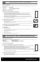
Hang using metal
handle hangers
Insert legs in each slot
Connecng Link Cords
and Power Cord
WHAT’S INSIDE
2 - Docks
4 - 18” legs (snap-on)
2 - Snap-in hangers
WHAT’S NEEDED
4 - Two or Four foot Modular Light Strips (JSFS2/JSFS4)
4 - Two or Four foot Snap-on Reectors (JSFR2/JSFR4)
3 - Modular Link Cords (JSFL)
MANUAL DE INSTRUCCIONES
COMPONENTES
2 - Bases
4 – Patas de 16 cm (enganche de clip)
2 – Ganchos de anclaje
ELEMENTOS NECESARIOS
4 – Barras de iluminación modular de 61 y 122 cm (JSFS2/JSFS4)
4 –Reectores de enganche de clip de 61 y 122 (JSFR2/JSFR4)
3 – Cables de enlace modular (JSFL)
Conexión de cables
de enlace y cable de
alimentación