SuperLogic 1500 Installation and Operation Manual 370 Encinal Street, Suite 150, Santa Cruz, CA 95060 (888) 426-5644, Fax (831) 336-9840 www.hydrologicsystems.
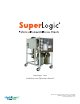
SuperLogic 1500 Manual - 1,500 gpd system.
SuperLogic 1500 Manual IntroducƟon Congratula ons on the purchase of your SuperLogic commercial reverse osmosis system. This is professional water purifica on equipment which, with proper care and maintenance can last you for many years. Feed water condi ons can vary dras cally as well as fluctuate at your specific site. In order retain your warranty, the provided opera ng log must be maintained and available for our review.
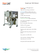
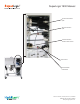
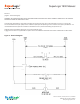
SuperLogic 1500 Manual Prefilter IN Gauge Prefilter OUT Gauge Vessel IN Gauge Vessel Out Gauge Sediment Prefilter Solenoid Valve TDS Monitor Brine/Concentrate Recircula on Valve Product Flowmeter Brine Flowmeter An -Scalant Pump/Motor Low Pressure Switch Carbon Prefilter Membrane/Vessel 370 Encinal Street, Suite 150, Santa Cruz, CA 95060 (888) 426-5644, Fax (831) 336-9840 www.hydrologicsystems.
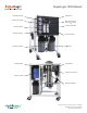
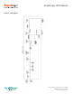
SuperLogic 1500 Manual Product Connec on 3/8” Brine Connec on 3/8” Feed Connec on Garden Hose Thread Flow Control Product Water Check Valve 370 Encinal Street, Suite 150, Santa Cruz, CA 95060 (888) 426-5644, Fax (831) 336-9840 www.hydrologicsystems.
SuperLogic 1500 Manual An -Scalant Cartridge: Allows the system to be operated at a 2:1 product to brine recovery ra o by preven ng membrane fouling due to hardness in the feed water. The system can also be specified for a 4:1 product to brine ra o if a proper water so ener or an scalant system is installed prior to the SuperLogic. Contact us for details @ (888) 426-5644.
SuperLogic 1500 Manual Pre-InstallaƟon Procedures PLEASE READ CAREFULLY. FAILURE TO FOLLOW THESE PROCEDURES CAN RESULT IN DAMAGE TO YOUR SYSTEM AND VOID YOUR WARRANTY. Packaging Upon delivery, inspect packaging and report any damage to your carrier immediately. A er unpacking the system, inspect it carefully for signs of damage. All damage claims should be made to the delivery carrier. OperaƟng Parameters The SuperLogic 1500 system may only be used on potable water.
SuperLogic 1500 Manual Figure 1 - Flow Diagram 370 Encinal Street, Suite 150, Santa Cruz, CA 95060 (888) 426-5644, Fax (831) 336-9840 www.hydrologicsystems.
SuperLogic 1500 Manual Electrical (Figure 2 - Electrical Diagram) WARNING! THE SYSTEM CAN START AT ANY TIME WHEN POWER IS CONNECTED. DO NOT CONNECT POWER UNTIL THE SYSTEM IS COMPLETELY INSTALLED AND READY TO RUN. The SuperLogic 1500 system is built with a standard 115v three-prong plug. Be sure the receptacle you use is on a circuit that has a Ground Fault Interrupter (GFCI) and has sufficient capacity for the opera ng current as listed in the system specifica ons.
SuperLogic 1500 Manual System Flush and Performance VerificaƟon Although SuperLogic 1500 systems are fully tested at the factory prior to shipping, it is recommended to flush and verify your system’s performance on-site. Flushing New membranes are shipped with a preserva ve that needs to be flushed out before use. Run the product line to drain while flushing the system. • • • • • • • Fully open the brine/concentrate recircula on valve by turning the knob counterclockwise.
SuperLogic 1500 Manual Low Pressure Switch Test While the system is running, shut off the water supply to the system. The system should shut off. If the system does not shut off a er ten seconds, either unplug the system or restore the water supply to the system. Call HydroLogic to diagnose problem. DO NOT LET THE SYSTEM RUN WITHOUT THE WATER SUPPLY TURNED ON. PUMP DAMAGE WILL OCCUR. Tank ConnecƟon Make the tank connec on as outlined on page 8.
SuperLogic 1500 Manual Filter/Membrane Replacement Schedule Sediment pre-filter - The 5 micron sediment filter is pleated and can be rinsed with a garden hose. You can rinse as o en as needed but it is recommended to replace this filter every 6 months. If you observe a 10 psi drop in the pre-filter out gauge from the psi in the pre-filter in gauge this indicates a clog in the sediment filter and you should either rinse it or replace it.
Limited Warranty This Limited Warranty extends to the original purchaser of the unit. This warranty covers all parts and factory labor needed to repair any manufacturer supplied item that proves to be defec ve material, workmanship or factory prepara on. The above-men oned warranty applies for the first full calendar year from the date of purchase.
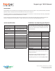
Date PSI OUT Filter PSI IN PPM Feed °F/°C PPM Product GPM PSI OUT Vessel PSI IN GPM Recovery Brine Rejection Comments
PANEL CUT-OUT DIAGRAM USER’S GUIDE 2 11/16 in. (68 mm) 2 11/16 in. (68 mm) 1. Using a knife, cut the diagram out (cut on the outer part of the line). 2. Align the cut-out to your panel and draw cut marks. 3. Cut the hole in the panel to the precise dimensions of the cut-out: 2-11/16 in. x 2-11/16 in. (68 mm x 68 mm) PS-200 --> See the installation section for complete instructions. PANEL MOUNT DUAL TDS CONTROLLER/MONITOR CONTACT DIAGRAM 8 9 10 AC 11 12 ALARM (BUZZ) 110-220V 13 N.C. 14 N.O.
Thank you for purchasing HM Digital’s PS-200. The PS-200 is a panel mount total dissolved solids (TDS) controller that monitors and controls levels of TDS in water. The controller has a maximum set point to help maintain a limit of TDS allowed in the product water, as well as a second sensor to monitor the TDS level of the feed water.
WARRANTY INSTALLATION INSTRUCTIONS IMPORTANT: Double-check your contacts prior to connecting the controller to a power source. Incorrect connections could result in shorting out the unit. ONE YEAR LIMITED WARRANTY The PS-200, including the controller and both sensors, is warranted by HM Digital, Inc. ("the Company") to the purchaser against defective materials and workmanship for one (1) year from the date of purchase. What is covered: Repair parts and labor, or replacement at the Company's option.
TROUBLESHOOTING Setting the Control Set Point 1. To set the control set point (to activate a device via the relay), press the SET button once. The EC reading will switch to a flashing number (the current set point). 2. Press the UP or DOWN buttons until the desired set point is reached. Pressing once will advance the reading by a single digit. Press and hold the button to advance the reading quickly. 3. Press the SET button again. This will save the set point to memory. 4.