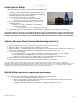
AQUA-LAB SD™ Chemical Dispensing System Operating Manual REV A
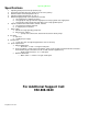
Operating Manual Specifications 1. 2. 3. 4. 5. 6. 7. 8. 9. 10. Operating water pressure: 200 psi (Factory set) Pneumatics operating pressure: 60-80 psi (for air valve systems) Maximum water source temperature 140° F Operating ambient temperature: 40-120° F Electrical supply(if pump system purchased from HFI) a. 120 single phase or 208/230 (3-phase) b. 1.5 hp pump 18 amps @ 120 volts single phase or 9 amps @ 230 volts single phase c. 1.5 hp pump 9 amps @ 230 volts three phase or 4.
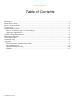
Operating Manual Table of Contents Illustrations ............................................................................................................................................. - 1 Initial Injector Setup ............................................................................................................................... - 2 Injector Vacuum Check .........................................................................................................................
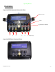
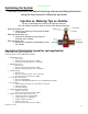
Operating Manual Illustration Aqua-Lab SD Air Operated Valve with Pilots Air Pilot Valve Valve Hydra-Cannon Manifold 1 2 3 4 5 6 Water Ports Aqua-Lab SD Electric Solenoid Valve © Hydra-Flex Inc 2011 -1-
Operating Manual Initial Injector Setup (Based on field experience this is HFI’s recommended staring point) 1. Using the recommended starting point (appendix page 10) or the target flow rate and the chemical dilutions chart (appendix) install the appropriate injector into each port 2. Connect pre-run solution lines to each Injector a. Be sure to use teflon tape when connecting the injector to the coupler to ensure there are no leaks 3.
Operating Manual Optimizing the System Consistently achieve the desired cleaning and presentation/performance using the least amount of chemical and water Injectors vs. Metering Tips vs. Nozzles The key to optimizing the system is through trial and error. Don’t be afraid to try these steps to achieve your ideal performance.
Operating Manual Chemical Usage Measuring Verify titration of chemicals before proceeding 1. Setup lab scale with small bucket of chemical to be measured. 2. Put the suction line into the bucket. 3. Run the application being tested to “prime” the line. (All air bubbles must be removed for accuracy) 4. Record the Initial Weight from the scale. (Tarring the scale with weight on the scale can affect accuracy) 5. Run the application for 6 vehicles (or manually for the same it would be on for 6 vehicles). 6.
Operating Manual Solenoid Valve Replacement 1. Start by removing the nut and washer from the top of the solenoid coil. 2. Remove the coil and set aside. 3. Unscrew and remove the valve assembly using the larger (1 1/8”) steel hex closest to the plastic manifold body. 4. Screw in new valve assembly 5. Set coil back on plunger and tighten down with nut and washer Air Operated Valve Replacement 1. Start by removing the air line from the elbow on the valve. 2.
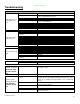
Operating Manual Troubleshooting PROBLEM POTENTIAL CAUSES Pump not primed Inlet Restriction Pump Operates, but delivers little or no water Pump won't start or run at full speed Missing 1 of 3 Phases Inadequate water supply Undersized piping Leak on the Inlet side Worn or defective pump parts Incorrect Motor rotation Blown fuse or circuit breaker Defective Motor Starter contactor Current Sensor set to high Thermal Overload set to low Incorrect Motor Voltage Defective motor E-Stop is depressed Pump compo
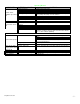
Operating Manual PROBLEM System won't regulate up to 200 psi Flow at arch is too low POTENTIAL CAUSES Pump not primed Debris in regulator Motor rotation incorrect Opening to many valves at once Defective Check Valve Defective Regulator Defective Pump Incorrect Injector Flow Rate Selection System pressure too low Foam Generator Plugged Downstream pluming restrictive Replace with desired injector size Solenoid valve malfunction Ensure valve is receiving the correct electrical signal and voltage Valve ma
Operating Manual Appendix © Hydra-Flex Inc 2011 -8-
Operating Manual Setup Starting Point Recommended Aqua-Lab Setup Starting Point Chemical Application Injector Range Air Nozzles Presoak 618057 618086 20 - 30 KSS12 X4 CTA 618040 618070 35 - 55 1080 X4 Wrap 618057 618070 10 - 20 App. Dep. Mitter 618057 618070 10 - 20 App. Dep. TriFoam Colors 618057 618070 10 - 20 App. Dep. Bug Blaster 618040 618057 App. Dep. App. Dep. Under Carriage 618051 618070 App. Dep. App. Dep.
Operating Manual Chem-Flex Injector Listing Aqua-Lab Chem Flex Injector Listing Part Number 618029 618040 © Hydra-Flex Inc 2011 # Barbs GPM 1 0.25 1 0.50 618051 618057 618070 618083 618086 618098 618125 629029 1 1 1 1 1 1 1 2 0.75 1.00 1.50 2.00 2.30 3.20 5.40 0.25 629040 629051 629057 629070 629083 629086 629098 629125 2 2 2 2 2 2 2 2 0.50 0.75 1.00 1.50 2.00 2.30 3.20 5.
Operating Manual AQUA-LAB WARRANTY Factory Limited Hydra-Flex Inc warrants its equipment to be free from defect in material or workmanship under proper normal proper use for a period of one (1) year beginning the date of purchase. The Hydra-Flex Inc’s liability shall be limited to repair or replacement of parts found to be defective within the warranty period and following Hydra-Flex Inc’s inspection.