AQUA-LAB™ CS1 Chemical Dispensing System Installation and Operation Manual REV A
Operating Manual For Additional Support Call: 952.808.3640 Table of Contents Specifications .......................................................................................................................................... - 1 Illustration ............................................................................................................................................... - 1 Installation and Set Up ..........................................................................................
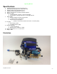
Operating Manual Specifications 1. 2. 3. 4. 5. 6. 7. 8. 9. 10. 11. Operating water pressure: 200 psi (Factory set) Pneumatics operating pressure: 100 psi Max Feed Maximum water source temperature 140° F Operating ambient temperature: 40-120° F Signal – No signal from Car Wash Controller required Electrical supply a. 120/208-230VAC (1-phase) – 8 foot cord included b. 3/4 hp pump 10 amps @ 120 volts or 5 amps @ 208 volts Water supply a. 50 micron filtration or better recommended b.
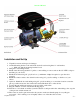
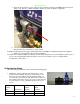
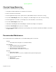
Operating Manual Adjustable Pressure Regulator Installation and Set Up 1. Unpack from crate and inspect for damages 2. Anchor Mounting bracket to the wall in the desired location using three ¼” wall anchors. a. Make sure that the mounting bracket is level 3. Hang CS1 on mounting bracket 4. Plumb water inlet using attached ½” push to connect fitting or remove and use the 3/8” NPT to adapt to the fitting of your choice. 5.
Operating Manual a. Increase the pressure set point of the pressure switch by removing the Phillips head screw and using a 1/8” hex key or Allen wrench to turn the set screw clockwise, replace the b. Increase the size of the nozzle on the gun c. Decrease the size of the injector on the system 12. Make sure that the pressure gage at the manifold is set at 200psi by adjusting the pressure regulator. a. Make sure to engage the lock nut after adjustment 13.
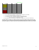
0.029 0.04 0.04 0.04 0.051 0.051 0.051 0.057 0.057 0.057 4 5 6 7 7 8 10 8 10 15 0.052 0.057 0.062 0.067 0.067 0.072 0.08 0.072 0.08 0.096 Operating Manual 15 50 25 10 50 40 15 60 45 18 2. Connect solution lines to the bug prep assembly using the attached push connect fitting a. Do not over tighten poly fittings or they may crack 3. Connect ¼” poly lines from each chemical container to the appropriate injector a. Ensure a foot valve or similar check valve/filter is installed on each line i.
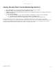
Operating Manual Injector Vacuum Check (for troubleshooting injectors) 1. At the ChemFlex injector, remove the chemical feed line from the injector hose barb. 2. Attach the tubing of the vacuum gauge to the ChemFlex hose barb 3. With the gun open and the system running an injector that is working properly will have a reading greater than or equal to (≥) 20 in Hg 4.
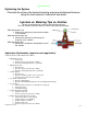
Operating Manual Optimizing the System Consistently achieve the desired cleaning and presentation/performance using the least amount of chemical and water Injectors vs. Metering Tips vs. Nozzles The key to optimizing the system is through trial and error. Don’t be afraid to try these steps to achieve your ideal performance.
Operating Manual Chemical Usage Measuring Verify titration of chemicals before proceeding 1. Setup lab scale with small bucket of chemical to be measured. 2. Put the suction line into the bucket. 3. Run the application being tested to “prime” the line. (All air bubbles must be removed for accuracy) 4. Record the Initial Weight from the scale. (Tarring the scale with weight on the scale can affect accuracy) 5. Run the application for 6 vehicles (or manually for the same it would be on for 6 vehicles). 6.
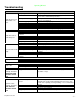
Operating Manual Troubleshooting PROBLEM POTENTIAL CAUSES Pump not primed Inlet Restriction Pump Operates, but delivers little or no water Pump won't start or run at full speed Inadequate water supply Undersized piping Leak on the Inlet side Worn or defective pump parts Pump check valves cloged Incorrect Motor rotation Blown fuse or circuit breaker Defective Motor Starter contactor Defective pressure switch Incorrect Motor Voltage Defective motor Pump components damaged SOLUTIONS See priming instructi
Operating Manual PROBLEM System won't regulate up to 200 psi Flow at gun is too low POTENTIAL CAUSES Follow priming instructions Remove regulator and clean out debris Verify rotation and adjust wiring to correct Clean and check all 6 pump check valves Replace check valve if broken Replace Regulator Replace Pump Incorrect Injector Flow Rate Selection System pressure too low Foam Generator Plugged Downstream pluming restrictive Replace with desired injector size Solenoid valve malfunction Ensure valve
Operating Manual Appendix © Hydra-Flex Inc 2011 - 10 -
Operating Manual Chem-Flex Injector Listing Aqua-Lab Chem Flex Injector Listing # Part Number Barbs GPM 618029 1 0.25 618040 1 0.50 © Hydra-Flex Inc 2011 618051 618057 618070 618083 618086 618098 618125 629029 1 1 1 1 1 1 1 2 0.75 1.00 1.50 2.00 2.30 3.20 5.40 0.25 629040 629051 629057 629070 629083 629086 629098 629125 2 2 2 2 2 2 2 2 0.50 0.75 1.00 1.50 2.00 2.30 3.20 5.
Operating Manual AQUA-LAB WARRANTY Factory Limited Hydra-Flex Inc warrants its equipment to be free from defect in material or workmanship under proper normal proper use for a period of one (1) year beginning the date of purchase. The Hydra-Flex Inc’s liability shall be limited to repair or replacement of parts found to be defective within the warranty period and following Hydra-Flex Inc’s inspection.