
Instruction Manual

HDA 5500 for HLB 1000 and CS 1000
- 20 -
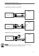
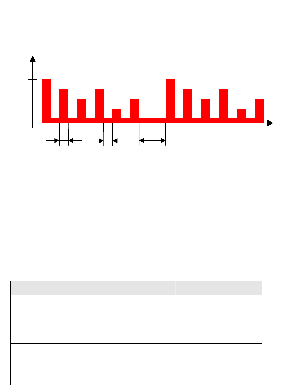
9.4 Sequential analogue output of the CS 1000
The analogue output signal of the measured values is output to
PIN 2 of the CS 1000 to the HDA 5500 sequentially as follows.
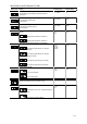
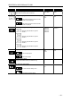
Explanation: Output of the sequential analogue output (each 4 .. 20 mA):
Start signal: 20 mA 2 s
Signal 1: Measurement ISO4 0 .. 24.4 2 s
Pause (4 mA) 2 s
Signal 2: Measurement ISO6 0 .. 24.4 2 s
Pause (4 mA) 2 s
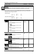
Signal 3: Measurement ISO14 0 .. 24.4 2 s
Pause (4 mA) 2 s
Signal 4: Measurement ISO21 0 .. 24.4 2 s
Pause (4 mA) 2 s
Signal 5: Status signal See table below for the signal
levels used 2 s
Pause before the next output cycle: 4 mA 30 s
Note: the setting ranges must be set in the basic menu.
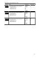
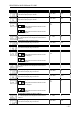
Status signal
Status display HAD 5500 Condition Level of status signal
0 CS working smoothly 5 mA
1 Device error / CS not ready 6 mA
2 Flow rate too low
(FLOW 2 LOW)
7 mA
3 Below the measuring limit
(ISO <9. <8. <7)
8 mA
4 No measured value
(Flow undefined)
9 mA
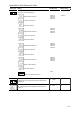
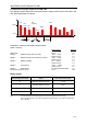
t
Start
Status
Start
20mA
4mA
I
2s 30s
2s
4
µ
m
6
µ
m
14
µ
m
21
µ
m