
Instruction Manual

HDA 5500 for HLB 1000 and CS 1000
- 19 -
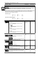
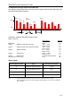
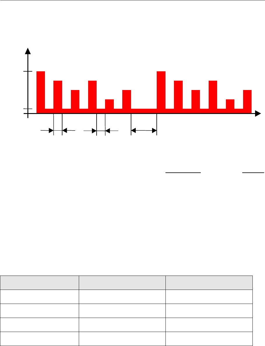
9.3 Sequential analogue output of the HLB 1000
The analogue output signal of the measured values is output at PIN 4 of the HLB 1000 to the
HDA 5500 sequentially, as follows:
t
S
tart
Rel.
Visco
Rel.
D
C
Rel.
humidity
Temp.
Status
S
tart
20mA
4mA
I
2
s
3
0s
2s
Explanation: Output of sequential analogue output:
(each 4..20 mA)
Output signal Duration
Start signal: 20 mA 2 s
Signal 1: Relative change in the viscosity -30% ... +30% 2 s
Pause (4 mA) 2 s
Signal 2: Relative change in the dielectric constant -30% ... +30% 2 s
Pause (4 mA) 2 s
Signal 3: Relative humidity 0% ... +100% 2 s
Pause (4 mA) 2 s
Signal 4: Temperature -25°C... +100°C 2 s
Pause (4 mA) 2 s
Signal 5: Status signal For levels see table below 2 s
Pause before the next cycle: 4 mA 30 s
Status signal
Status display HDA 5500 Status Level of the status signal
0 Reference phase (no error) 5 mA
1 Function phase (no error) 7 mA
2 or 3 Fluid condition out of range 9 or 11 mA
4 to 7 Internal error 13 to 19 mA
Note: The exact description of the status signal can be found in the Manual for the HLB 1000.
Due to possible tolerances, we recommend setting the threshold approx. 0.25 mA below the ideal value
given in the table.