Digital Display Unit HDA 5500 for Oil Condition Sensor HLB 1000 and Contamination Sensor CS 1000 User Manual HDA 5500-0-2-AC-006 (CM1k) HDA 5500-0-2-DC-006 (CM1k) Status: Part No. 25.06.
HDA 5500 for HLB 1000 and CS 1000 CONTENTS 1 Introduction 1.1 European standards compatibility 3 3 2 Safety instructions 3 3 Functions 3 4 Operating keys 4 5 Selecting and displaying the unit of measurement 4 6 Installation and commissioning 6.1 Mechanical installation 6.2 Electrical connection 6.3 Supply voltage 5 5 5 6 7 Programming 7.1 Adjusting the basic settings 7.2 Overview of basic settings menu 7 7 8 8 Connecting the Oil Condition Sensor HLB 1000 / Contamination Sensor CS 1000 8.
HDA 5500 for HLB 1000 and CS 1000 1 Introduction The individual components and the final assembly of the Digital Display Unit HDA 5500 are subject to strict quality controls. Each HDA 5500 is individually calibrated and subjected to a final test. In this way we can guarantee that the unit is fault-free on despatch and conforms to the given specifications. However, if there is a cause for complaint, please return the unit to us outlining the fault.
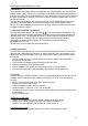
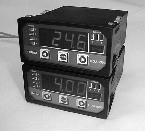
HDA 5500 for HLB 1000 and CS 1000 4 Operating keys 4-digit digital display LED display of active switching points Sensor Relais 1 2 LED display of active sensor 1 2 3 3 % 4 MODE HDA5500 Display of unit of measurement sensor 1, 2, 3 or 4 Keys for adjusting the switching points, switch-back points and the menu functions 5 Selection and display of the unit of measurement The operator can select the appropriate unit label from a printed sheet and this is then displayed with background lighting.
HDA 5500 for HLB 1000 and CS 1000 6 Installation and commissioning 6.1 Mechanical installation The HDA 5500 is a control panel unit with a standard mounting housing 96 x 48 mm and requires a control panel cut-out: 92 x 45 mm • Control panel thickness: at least 1.25 mm • Mounting depth: at least 150 mm Panel clips Panel thickness Clamping guides 6.
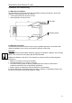
HDA 5500 for HLB 1000 and CS 1000 6.3 Supply voltage The supply voltage is connected to terminal X1. 12..32 VDC HDA 5500–0–2–DC–XXX (see type code label) 85..265 VAC 50 / 60 Hz HDA 5500–0–2–AC–XXX (see type code label) After switching on the supply voltage, the unit displays HdA for approximately 2 s. Then the number of the sensor set as the primary display is shown. After a further 2 s (approx.) the actual value is displayed.
HDA 5500 for HLB 1000 and CS 1000 7 Programming In order to adapt the unit to a particular application, the HDA 5500 is programmed by varying the basic settings. The basic settings are combined in a menu. Important: When the menu is activated, no switching functions are carried out. 7.1 Adjusting the basic settings To change the basic settings, the menu must be activated. Procedure for activating the menu: • During normal operation, press the MODE key and hold down for at least 5 s.
HDA 5500 for HLB 1000 and CS 1000 7.2 Overview of basic settings menu Menu point Setting Device: Setting range HLB, CS Default setting HLB r.ViS. r.diE. r.HuM. TEMP. r.ViS. SP Win SP on oFF on 0..99.99 s 0 0..99.99 s 0 r.ViS. r.diE. r.HuM. TEMP. SP Win on oFF 0..99.99 s 0..99.99 s r.ViS.
HDA 5500 for HLB 1000 and CS 1000 Menu point Setting Switching function switching output 3 (S.S.3) Similar to switching output 1 (see above), and likewise for: • Switching mode (S.M.3) • Switching direction (S.d.3) • Switch-on delay (T.on.3) • Switch-off delay (T.oF.3) Switching function switching output 4 (S.S.4) Similar to switching output 1 (see above), and likewise for: • Switching mode (S.M.4) • Switching direction (S.d.4) • Switch-on delay (T.on.4) • Switch-off delay (T.oF.4) Setting range r.ViS.
HDA 5500 for HLB 1000 and CS 1000 Menu point Setting Decimal place for display of rel. change in viscosity (dEc.V.) Decimal place(s) when displaying measured values of rel. change in viscosity Setting range Default setting 0 .. 0.000 0.0 -999..9899 -30.0 -899..9999 30.0 on oFF on 0 .. 0.000 0.0 -999..9899 -30.0 -899..9999 30.0 on oFF on 0 .. 0.000 0.0 -999..9899 0.0 -899..9999 100.0 on oFF on Lower display range of rel. change in viscosity (LOr.V.
HDA 5500 for HLB 1000 and CS 1000 Menu point Setting Decimal place for display of temperature (dEc.T.) Decimal place(s) when displaying measured values of temperature Setting range Default setting 0 .. 0.000 0.0 -999..9899 -25.0 -899..9999 100.0 on oFF oFF r.ViS. r.diE. r.HuM. TEMP. r.ViS. MA VoLT VoLT YES no no Lower display range of temperature (LOr.T.) Lower limit of the display range of temperature Upper display range of temperature (Hir.T.
HDA 5500 for HLB 1000 and CS 1000 Menu point Setting Setting range Default setting When CS 1000 is selected Important: The default settings of the upper and lower limits of channels 1 to 4 (LO.1 to LO.4 and Hi.1 to HI.4) correspond to the values for operating the HLB 1000 on the HDA 5500. When operating the CS1000 on the HDA5500 please note that: The default setting ranges pre-set in the CS 1000 for the analogue signal output forms HDA.ISO, HDA.SAE or HDA.NAS must be changed as follows. HDA.
HDA 5500 for HLB 1000 and CS 1000 Menu point Setting Allocation of switching output 2 (S.S.2) Similar to switching output 1 (see above), and likewise for: • Switching mode (S.M.2) • Switching direction (S.d.2) • Switch-on delay (T.on.2) • Switch-off delay (T.oF.2) Allocation of switching output 3 (S.S.3) Similar to switching output 1 (see above), and likewise for: • Switching mode (S.M.3) • Switching direction (S.d.3) • Switch-on delay (T.on.3) • Switch-off delay (T.oF.
HDA 5500 for HLB 1000 and CS 1000 Menu point Setting Primary display (PriM) Setting range Default setting Channel 1 Channel 2 Channel 3 Channel 4 Channel 1 Value which is normally displayed: Measured value Channel 1 Lowest value Channel 1 Peak value Channel 1 Measured value Channel 2 Channel 1 Channel 2 Channel 3 Channel 4 Lowest value Channel 2 Peak value Channel 2 Measured value Channel 3 Channel 1 Channel 2 Channel 3 Channel 4 Lowest value Channel 3 Peak value Channel 3 Measured value C
HDA 5500 for HLB 1000 and CS 1000 Menu point Setting Lower display range of channel 1 (LO.1.) Lower limit of display range of channel 1 Setting range Default setting -999..9899 -30.0 -899..9999 30.0 on oFF on 0 .. 0.000 0.0 -999..9899 -30.0 -899..9999 30.0 on oFF on 0 .. 0.000 0.0 -999..9899 0.0 -899..9999 100.0 on oFF on 0 .. 0.000 0.0 -999..9899 -25.0 Upper display range of the channel (Hi.1.
HDA 5500 for HLB 1000 and CS 1000 Menu point Setting Upper display range of temperature (Hi.4.) Upper limit of the display range of channel 4 Setting range Default setting -899..9999 100.0 on oFF oFF Channel 1 Channel 2 Channel 3 Channel 4 Channel 1 MA VoLT VoLT YES no no Background lighting for the unit label for Channel 4(uni.4.
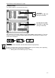
HDA 5500 for HLB 1000 and CS 1000 8 Connecting the oil condition sensor HLB 1000 8.1 HDA 5500 and oil condition sensor HLB 1000 HDA 5500-0-2-AC-006 (CM1k) + UB Signal 1 HLB 1000 GND Signal 2 1 X2.6 2 +12 V X2.5 AGND X2.7 IN1 3 4 HDA 5500-0-2-DC-006 (CM1k) +UB Signal 1 HLB 1000 1 2 X1(+) 12..32V X1(-) GND 3 X2.5 Signal 2 4 X2.7 12..32VDC AGND AGND IN1 8.2 HDA 5500 and Contamination Sensor 1000 9..36V DC 9..36V DC GND CS1000 AGND Analog OUT HDA 5500-0-2-AC/DC-006 (CM1k) 1 3 4 2 X2.
HDA 5500 for HLB 1000 and CS 1000 9 Digital display 9.1 Standard display Point 7.2 lists the options which you can select as the primary display. The value set at any one time is displayed permanently. Hints: • Initialisation of the HYDACLab ® can take up to 2 minutes; only once the initialisation has been completed are the measured values meaningful. • If the measured value exceeds the upper display range of the HDA 5500, then the measured value can no longer be displayed. The upper display range flashes.
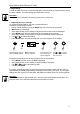
HDA 5500 for HLB 1000 and CS 1000 9.3 Sequential analogue output of the HLB 1000 The analogue output signal of the measured values is output at PIN 4 of the HLB 1000 to the HDA 5500 sequentially, as follows: I Start 20mA Rel. Visco Rel. humidity Start Rel. DC Status Temp. 4mA 2s t 30s 2s Explanation: Output of sequential analogue output: (each 4..
HDA 5500 for HLB 1000 and CS 1000 9.4 Sequential analogue output of the CS 1000 The analogue output signal of the measured values is output to PIN 2 of the CS 1000 to the HDA 5500 sequentially as follows. I Start Start 20mA 4µm 14µm Status 6µm 21µm 4mA 2s t 30s 2s Explanation: Output of the sequential analogue output (each 4 ..
HDA 5500 for HLB 1000 and CS 1000 10 Output response The HDA 5500 has an analogue output which is proportional to an input signal. The analogue output can be allocated to each of the signals (rel. change in viscosity, rel. change in dielectric constant, rel. humidity, temperature when device HLB 1000 is selected, or CH1, CH2, CH3 or CH4 when device CS 1000 is selected). 10.1 Analogue output On the analogue output a 4..20 mA or 0..10 V signal is available.
HDA 5500 for HLB 1000 and CS 1000 10.2 Switching outputs Each switching output consists of a relay, the switching contacts of which can be connected as N/C or N/O. For each switching output, the following parameters can be set during normal operation (see Point 7.2 Overview of the Basic Settings Menu): • Assignment to sensor signal • Switching function (switch point and hysteresis or switching window mode) • Switching direction (relay activated or relay deactivated) • Switch-on delay • Switch-off delay 10.
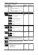
HDA 5500 for HLB 1000 and CS 1000 Example for switching output 1 (relay activated): Measured variable Off hi.1 plus 1% FS hi.1 Switch-back value Switching value Safety Zone On On Lo.1 Lo.1 minus 1% FS Switching value Switch-back value Safety Zone Off t On Off Abbreviations: "HI 1" to "HI 4" = High level 1 to 4 = upper switch point 1 or 4 "Lo 1" to "Lo 4"= Low level 1 to 4 = lower switch point 1 or 4 "FS" (Full Scale) = relative to full measuring range 10.
HDA 5500 for HLB 1000 and CS 1000 11 Adjusting switch points and hystereses • During normal operation, press mode key. • Depending on the settings SP (switch points) or Win (switching window) will be displayed Note: If the mode key is pressed for longer than approximately 5 s, then the Basic Settings Menu will be activated! 11.1 Switching outputs Procedure for HDA 5500 with switching output set to switch point and hysteresis mode: • During normal operation, press the mode key.
HDA 5500 for HLB 1000 and CS 1000 mode mode Press mode key Use the keys or to change the setting Release mode key Note: • If when pressing or Loc appears in the display, this shows that programming is disabled. To enable programming, see Point 12 Programming enable. or to scroll quickly through the values in the display. • Hold down 12 Programming enables The unit has two types of programming enable, the operating programming enable and the main programming enable.
HDA 5500 for HLB 1000 and CS 1000 12.2 Altering the main programming enable The main programming enable can only be altered when switching on the HDA 5500. If the HDA 5500 is already in operation, then the supply voltage must first be switched off or the HDA 5500 must be disconnected from the supply voltage. Procedure: • When switched off, press both arrow keys simultaneously and hold down. • Switch on or connect the supply voltage and at the same time continue to hold down the arrow keys for at least 3 s.
HDA 5500 for HLB 1000 and CS 1000 13 Technical specifications Display range Display 4-digit 7-segment LED display, red, height of digits 14.2 mm 3 LEDs for active sensor 4 LEDs for switching relays Display range - 999..9999 (adjustable by user) Display units (of measurement) with background lighting °C,°F, % (cut required unit label from sheet and slide it into the slot on the side) Input data Analogue signal input(s) Measuring range 4 .. 20 mA, sequential (HLB compatible) Accuracy class ± 0.
HDA 5500 for HLB 1000 and CS 1000 14 Model code HDA 5500 Order details HDA 5 5 0 0 – 0 – 2 – XX – 006 Inputs 0 = One analogue input Outputs 2 = Four relay outputs Supply voltage AC = 85..265 VAC DC = 12..
HDA 5500 for HLB 1000 and CS 1000 15 Unit dimensions Control panel thickness Control panel cut-out - 29 -
HDA 5500 for HLB 1000 and CS 1000 16 Electrical connections Model 1 Model 2 Model 3 Supply voltage plug X1 UNIT X1 PIN DESCRIPTION HDA 5500 – X – X – AC – 000 ~ / ~ HDA 5500 – X – X – DC – 000 + / - Models Supply voltage inputs 85VAC to 265VAC 50/60Hz 1 , 2 and 3 Supply voltage inputs 24VDC 1 , 2 and 3 Signals plug X2 X2 UNIT 1 2 3 HDA 5500 – 0 – X – XX – 000 RXD TXD DGND HDA 5500 – 1 – X – XX – 000 RXD TXD DGND HDA 5500 – 2 – X – XX – 000 RXD TXD DGND HDA 5500 – 3 – X – XX – 00
HDA 5500 for HLB 1000 and CS 1000 17 Error messages If an error is detected, then a corresponding error message appears which must be acknowledged by pressing any key. Possible error messages are as follows: Er.01 The switching points and hystereses have been set in such a way that the resulting switch-back point is no longer within the permissible setting range. Example: Switching point is set to 80%, the hysteresis to 100%. Action: Correct the hysteresis setting. Er.