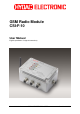
GSM Radio Module CSI-F-10 User Manual English (translation of original instructions) Status 29.01.2009 HYDAC ELECTRONIC GMBH Part.-Nr.
GSM Radio Module CSI-F-10 Status 29.01.2009 HYDAC ELECTRONIC GMBH Page 2 Part.-Nr.
GSM Radio Module CSI-F-10 Page 3 Table of Contents 1 2 3 4 5 General...........................................................................................................................9 1.1 Previous Knowledge..............................................................................................9 1.2 Structure of the Manual.........................................................................................9 1.3 Copyright Protection ..............................................
GSM Radio Module CSI-F-10 Page 4 6.4 Voltage supply with communication via direct connection to Portable Data Recorder HMG 510..........................................................................................................34 6.4.1 Device Connection..........................................................................................35 6.4.2 Connection Setup ...........................................................................................36 6.
GSM Radio Module CSI-F-10 9.2.8 9.2.9 Page 5 Error Event......................................................................................................85 Boolean Constants .........................................................................................85 9.3 Numerical Calculations .......................................................................................86 9.3.1 Addition..........................................................................................................
GSM Radio Module CSI-F-10 Page 6 9.8 Other Boolean Operations ................................................................................103 9.8.1 Note Switching Status...................................................................................103 9.8.2 Switching Delay ............................................................................................103 9.8.3 T - Flipflop.....................................................................................................104 9.8.
GSM Radio Module CSI-F-10 11 Page 7 Specifications ........................................................................................................114 11.1 Power Supply .....................................................................................................114 11.2 Sensor Inputs (5 pole female connection "Sensor 1", 8 pole female connection "Sensor 2")................................................................................................114 11.
GSM Radio Module CSI-F-10 Page 8 Preface We have compiled the most important instructions for the operation and maintenance of our product for you, its user, in this documentation. It will acquaint you with the product and assist you in using it as intended in an optimal manner. Keep it in the vicinity of the product so it is always available. Note that the information on the unit's engineering contained in the documentation was that available at the time of publication.
GSM Radio Module CSI-F-10 Page 9 1 General This manual is a constituent part of the device. It contains texts and graphics concerning the correct handling of the product and must be read before installation, assembly and the operation of the device. The manual offers information concerning the safe operation, installation and programming of the GSM radio module CSI-F-10. It is aimed at engineers, programmers, fitters and maintenance personnel with a general knowledge of automation technology.
GSM Radio Module CSI-F-10 Page 10 Danger means that death, severe bodily injury or considerable property damage will occur if the respective precautionary measures are not implemented. Warning means that death, severe bodily injury or considerable property damage could occur if the respective precautionary measures are not implemented. Caution means that some non-severe bodily injury or property damage could occur if the respective precautionary measures are not implemented.
GSM Radio Module CSI-F-10 Page 11 2 Safety 2.1 General Safety Precautions Follow the specifications contained in this description. Non-observance of the instructions, operation in applications other than those outlined below, incorrect installation/assembly or incorrect handling of the product can be severely detrimental to the safety of personnel and systems/machines and will invalidate warranty and liability claims.
GSM Radio Module CSI-F-10 Page 12 2.2 Antenna Operating the radio module without attaching the antenna or when the antenna is faulty, can damage the unit. 2.3 Electronic Devices Operating the CSI-F-10 can under certain circumstances adversely affect the functioning of other electronic devices if they are not screened correctly. Please contact the manufacturer of the particular device in the event of failure. Do not operate the GSM radio module CSI-F-10 in the vicinity of medical equipment! 2.
GSM Radio Module CSI-F-10 Page 13 3 Proper/Designated Use The GSM radio module CSI-F-10 is an electronic unit with universal application for transferring data and digital signals via the GSM mobile radio network. The device can be used in both stand-alone operation and as a GSM modem on a CMU 1000 (HYDAC Condition Monitoring Unit). A maximum of two HYDAC SMART sensors with HSI interface (automatic sensor recognition), e.g. HYDACLab®, AS 1000 or CS 1000, can be connected to its input connections.
GSM Radio Module CSI-F-10 Page 14 The two basic operating modes available for using the GSM radio module CSI-F-10 are described below: 3.1 Stand alone operation The CSI-F-10 transmits the measured values and additional information of the connected sensors directly and without processing them (passive mode) or monitors and processes the input signals with a "CM program" stored in the unit (active mode).
GSM Radio Module CSI-F-10 Page 15 4 Installation 4.1 Unpacking The CSI-F-10 is supplied in a cardboard box. When taking delivery and when unpacking the unit, check it for transit damage and report any damage to the carrier immediately. 4.2 Installing the Unit Only fit the unit in locations where the radio module can be operated without risk (see Chapter 2. Safety).
GSM Radio Module CSI-F-10 Page 16 5 Setup and Function The GSM radio module CSI-F-10 is an electronic device with universal applications for transmitting data and digital signals over the GSM mobile radio network. A maximum of two HYDAC SMART sensors with HSI interface (automatic sensor recognition), e.g. HYDACLab®, AS 1000 or CS 1000, can be connected to its input connections. 5.
GSM Radio Module CSI-F-10 Page 17 5.2 Pin connections Plug Power Plug Sensor 1 (AS 1000 HLB 1000) Plug Sensor 2 (CS 1000) Plug In / Out Status 29.01.2009 Pin 1 2 3 4 5 I/O Function I/O +UB (in) n.c. 0V n.c. HSI Pin 1 2 3 4 5 +UB (out) n.c. n.c. 0V HSI Pin 1 2 3 4 5 6 7 8 IN / OUT Function +UB (out) n.c. 0V n.c. HSI n.c. n.c. n.c.
GSM Radio Module CSI-F-10 Page 18 5.3 Connection examples for sensors Warning! The total length of the connected sensor cables (Sensor 1 + Sensor 2) may not exceed max. 40 m. If this 40 m length is exceeded, there can be problems with the HSI signal transmission. 5.3.1 HYDACLab® to Connection 1 and CS 1000 to Connection 2 In this case, only voltage supply for CS 1000! ZBE 38 Voltage supply / HSI see Chap. 6.3 to 6.6 8 pole, max. 30m 5 pole, max. 30m 5 pole, max. 30m In total max.
GSM Radio Module CSI-F-10 Page 19 5.3.2 AS 1000 to Connection 1 and CS 1000 to Connection 2 In this case, only voltage supply for CS 1000! ZBE 38 Voltage supply / HSI see Chap. 6.3 to 6.6 8 pole, max. 30m 5 pole, max. 30m 5 pole, max. 30m ZBE 36 In total max. 40m A ZBE 41 B HSI Address "a" HSI Address "b" Status 29.01.2009 HYDAC ELECTRONIC GMBH Part.-Nr.
GSM Radio Module CSI-F-10 Page 20 5.3.3 HYDACLab® and AS 1000 to Connection 1 ZBE 38 Voltage supply / HSI see Chap. 6.3 to 6.6 5 pole, max. 30m in total max. 40m A HSI Address "a" ZBE 26 AA B ZBE 36 5 pole, max. 30m ZBE ZBE26 41 BB HSI Address "b" Note! Regardless of the type of constellation, a maximum of 2 SMART sensors can be connected to the CSI-F-10 and evaluated by the device. The connected sensors must already be addressed using the HSI addresses "a" and "b".
GSM Radio Module CSI-F-10 Page 21 Connection to Condition Monitoring Unit CMU 1000 max. 30m 5 4 3 2 1 +UB 0V HSI 18..35 V DC / 3.5 A Note! For this connection option, the CMU 1000 can either be configured via the CSI-F-10, or the CSI-F-10 can be configured via the CMU 1000. In addition the CSI-F-10 acts as the GSM modem to the CMU 1000, to forward data and / or messages sent from this unit (see Chap. 3.2.).
GSM Radio Module CSI-F-10 Page 22 6 Commissioning Note! In order to be able to communicate later with the CSI-F-10 via GSM mobile radio, this must first be configured. This means that the mobile phone numbers which are authorized for access must be stored in the CSI-F-10 and appropriate permissions assigned. In order to configure the GSM radio module CSI-F-10, first connect directly with the GSM radio module CSI-F-10 (via CSI-B-2, HMG 510 or CMU 1000). ►See Chapter 6.3, 6.4 and 6.5! 6.
GSM Radio Module CSI-F-10 Page 23 PIN deactivation If the PIN number is not input correctly or in full, during commissioning the SIM card can be blocked. We recommend therefore that the PIN of the SIM card is deactivated. To deactivate the PIN code, place the SIM card in a mobile telephone and follow the device menu to deactivate the PIN request.
GSM Radio Module CSI-F-10 Page 24 6.3 Voltage supply with communication via direct connection with interface module CSI-B-2 If a GSM radio module is connected to the PC via an adaptor such as the HYDAC interface module CSI-B-2, then the GSM radio module has the HSI address "Bus master". If further sensors are connected to the CSI-F-10, these must be addressed with the normal HSI address "a" or "b".
GSM Radio Module CSI-F-10 Page 25 6.3.1 Device Connection • • • Connect the RS232 serial interface of your PC with the 9-pin SUB-D socket of the HYDAC interface module CSI-B-2 via a corresponding data cable (or RS485 via terminal block). Connect the CSI-F-10 to the CSI-B-2 via the HSI connection -X2 / Pin 3 and 4 on the CSI-B-2 Connection B / Pin 4 and 5 on ZBE 26 on the CSI-F-10 Connect the voltage supply to the CSI-F-10 GSM radio module according to the diagram. A ZBE 26 B 18..
GSM Radio Module CSI-F-10 Page 26 6.3.2 Connection Setup • • Start the HYDAC PC software CMWIN In the Units Menu, select the "CM Manager" option. • If the Connection window does not open automatically, select "Connection" in the menu bar of the CM Manager. Select the option "Direct connection" in the window that opens. Click on "Change" in the top line to open the window for the interface settings.
GSM Radio Module CSI-F-10 Page 27 • In the Interface field, select the option "Open" in order to open the selected interface (COM port). The opened interface will be indicated by a green dot on the right-hand edge of the window. • In the Sensor field, specify whether you would like to connect to CSI-F-10 GSM radio module direct or to one of the sensors connected to it. Afterwards, proceed according to the three options described below.
GSM Radio Module CSI-F-10 Page 28 6.3.2.1 Connecting to the CSI-F-10 • Via "Change" in the Bus address line, open the selection window for the bus address and select "Bus master". Change... • • • • • Afterwards click on "Connect" in the Sensor field to connect the CSI-F-10 to the PC. The successful connection will be symbolized by a green dot on the right-hand edge of the window. Pressing "Disconnect" in the Sensor field allows you to break the existing connection between the CSI-F-10 and PC again.
GSM Radio Module CSI-F-10 • Page 29 The following window opens after the connection has been successfully established: The menu structure and window properties of the CM Manager are explained below in greater detail in Chapter 7. Status 29.01.2009 HYDAC ELECTRONIC GMBH Part.-Nr.
GSM Radio Module CSI-F-10 Page 30 6.3.2.2 Connecting to the sensor by connection 1 (HSI address "a") • Click on "Disconnect" under Connection in the Device box to break the existing PC connection with the CSI-F-10. • The following window opens: • Then click on "No", so that the bus master is not reactivated. • (!)1 • Select Change in the Bus address line.
GSM Radio Module CSI-F-10 Page 31 • The following window opens: • • Select the appropriate device (Address a in our example). Confirm this with OK. • Click on Connect to establish a link with the sensor. • Successful establishment of the connection will be signaled as shown below: • Click on Ok to establish the connection setup or on Disconnect to cancel the connection setup. Status 29.01.2009 address HYDAC ELECTRONIC GMBH in the selection window Part.-Nr.
GSM Radio Module CSI-F-10 Page 32 6.3.2.3 Connecting to the sensor by connection 2 (HSI address "b") • Click on "Disconnect" under Connection in the Device box to break the existing PC connection with the CSI-F-10. • The following window opens: • Then click on "No", so that the bus master is not reactivated. • (!)1 see Page 30 • Select Change in the Bus address line. Status 29.01.2009 HYDAC ELECTRONIC GMBH Part.-Nr.
GSM Radio Module CSI-F-10 Page 33 • The following window opens: • • Select the appropriate device (Address b in our example). Confirm this with OK. • Click on Connect to establish a link with the sensor. • Successful establishment of the connection will be signaled as shown below: • Click on Ok to connect the connection setup or on Disconnect to cancel the connection setup. Status 29.01.2009 address HYDAC ELECTRONIC GMBH in the selection window Part.-Nr.
GSM Radio Module CSI-F-10 Page 34 6.4 Voltage supply with communication via direct connection to Portable Data Recorder HMG 510 If a GSM radio module is connected via a HYDAC Portable Data Recorder HMG 510 to the PC, then the GSM radio module has the HSI address "Bus master". If other sensors are connected to the CSI-F-10, these must be addressed using a normal HSI address "a" or "b".
GSM Radio Module CSI-F-10 Page 35 6.4.1 Device Connection • • • Connect a USB port on your PC with the USB socket of the HYDAC Portable Data Recorder HMG 510 via an appropriate data cable (USB cable is supplied with the HMG 510). Connect the CSI-F-10 with the HMG 510 using a 5-pole M12x1 sensor cable (e.g. ZBE 30-02 or ZBE 30-05) Connect the voltage supply to the CSI-F-10 GSM radio module according to the diagram. A ZBE 26 B USB M12x1, 5-pole Power supply 10,5..35 V D C Status 29.01.
GSM Radio Module CSI-F-10 Page 36 6.4.2 Connection Setup • • Start the HYDAC PC software CMWIN In the Units Menu, select the "CM Manager" option. • If the Connection window does not open automatically, select "Connection" in the menu bar of the CM Manager. Select the option "Direct connection" in the window that opens. Click on "Change" in the top line to open the window for the interface settings.
GSM Radio Module CSI-F-10 Page 37 • In the Interface field, select the option "Open" in order to open the selected interface (COM port). The opened interface will be indicated by a green dot on the right-hand edge of the window. • In the Sensor field, specify whether you would like to connect to the CSI-F-10 GSM radio module direct, or to one of the sensors connected to it. • • Click on "Change" to open the window for the pass-through mode.
GSM Radio Module CSI-F-10 Page 38 6.4.2.1 Connecting to the CSI-F-10 • Via "Change" in the Bus address line, open the selection window for the bus address and select "Bus master". • Afterwards click on "Connect" in the Sensor field to connect the CSI-F-10 to the PC. The successful connection will be symbolized by a green dot on the right-hand edge of the window. • • • • Pressing "Disconnect" in the Sensor field allows you to break the existing connection between the CSI-F-10 and PC again.
GSM Radio Module CSI-F-10 • Page 39 The following window opens after the connection has been successfully established: The menu structure and window properties of the CM Manager are explained below in greater detail in Chapter 7. Status 29.01.2009 HYDAC ELECTRONIC GMBH Part.-Nr.
GSM Radio Module CSI-F-10 Page 40 6.4.2.2 Connecting to the sensor by connection 1 (HSI address "a") • Click on "Disconnect" in the Device box to break the existing PC connection with the CSI-F-10. • The following window opens: • Then click on "No", so that the bus master is not reactivated. • (!)1 • Select Change in the Bus address line.
GSM Radio Module CSI-F-10 Page 41 • The following window opens: • • Select the appropriate device (Address a in our example). Confirm this with OK. • Click on Connect to establish a link with the sensor. • Successful establishment of the connection will be signaled as shown below: • Click on Ok to establish the connection setup or on Disconnect to cancel the connection setup. Status 29.01.2009 address HYDAC ELECTRONIC GMBH in the selection window Part.-Nr.
GSM Radio Module CSI-F-10 Page 42 6.4.2.3 Connecting to the sensor by connection 2 (HSI address "b") • Click on "Disconnect" in the Device box to break the existing PC connection with the CSI-F-10. • The following window opens: • Then click on "No", so that the bus master is not reactivated. • (!)1 see Page 40 • Select Change in the Bus address line. Status 29.01.2009 HYDAC ELECTRONIC GMBH Part.-Nr.
GSM Radio Module CSI-F-10 Page 43 • The following window opens: • • Select the appropriate device (Address b in our example). Confirm this with OK. • Click on Connect to establish a link with the sensor. • Successful establishment of the connection will be signaled as shown below: • Click on Ok to establish the connection setup or on Disconnect to cancel the connection setup. Status 29.01.2009 address HYDAC ELECTRONIC GMBH in the selection window Part.-Nr.
GSM Radio Module CSI-F-10 Page 44 6.5 Voltage supply with communication via GSM mobile radio connection (standard application) Note! In order to be able to communicate with the CSI-F-10 using GSM mobile radio, this must first be configured. This means that the mobile phone numbers which are authorized for access must be stored in the CSI-F-10 and appropriate permissions assigned.
GSM Radio Module CSI-F-10 Page 45 6.5.1 Device connection • • • Connect your PC with a standard GSM modem and make sure the device is ready for operation. Insert a valid SIM card into the CSI-F-10 GSM radio module (see Chap. 6.1). Connect the voltage supply to the CSI-F-10 GSM radio module according to the diagram. GSM 1 2 3 4 5 PIN 5 Not to connect! 10.5..35 V DC / 3.5 A 6.5.2 Connection Setup • • Start the HYDAC PC software CMWIN In the Units Menu, select the "CM Manager" option.
GSM Radio Module CSI-F-10 • • • • • • • • • Page 46 Make the corresponding preselection for the port settings in the window that opens under Interface selection. Select the relevant port address and Baud rate (9600 for GSM) under Interface settings. Click "Refresh" to update the interfaces marked under Interface selection in terms of availability. Click on “OK“ to apply the modified settings or “Cancel“ to discard these changes. In either case you will then return to the Connection window.
GSM Radio Module CSI-F-10 Page 47 • Click on “Open” to open the selected interface. The opened interface is then indicated by a green dot at the top right. (Warning: The selection process can take up to a minute!) • Click on "Change" to open the window for the pass-through mode and then proceed according to the options described below. Status 29.01.2009 HYDAC ELECTRONIC GMBH Part.-Nr.
GSM Radio Module CSI-F-10 Page 48 6.5.2.1 Connecting to the CSI-F-10 • Select No address and then Switch off. The following message appears • Confirm this with OK. • Click on Connect to establish a link with the CSI-F-10. • Click on Ok to establish the connection setup or on Disconnect to cancel the connection setup. Status 29.01.2009 HYDAC ELECTRONIC GMBH Part.-Nr.
GSM Radio Module CSI-F-10 • Page 49 The following window opens after the connection has been successfully established: The menu structure and window properties of the CM Manager are explained below in greater detail in Chapter 7 ff. Status 29.01.2009 HYDAC ELECTRONIC GMBH Part.-Nr.
GSM Radio Module CSI-F-10 Page 50 6.5.2.2 Connecting to the sensor by connection 1 (HSI address "a") • Select Address a and then Switch on. The following message appears • Confirm this with OK. • Click on Connect to establish a link with the sensor. • Click on Ok to continue with the connection setup or on Disconnect to cancel the connection setup. Status 29.01.2009 HYDAC ELECTRONIC GMBH Part.-Nr.
GSM Radio Module CSI-F-10 Page 51 6.5.2.3 Connecting to the sensor by connection 2 (HSI address "b") • Select Address b and then Switch on. Afterwards the following message appears: • Confirm this with OK. • Click on Connect to establish a link with the sensor. • Click on Ok continue with the connection setup or on Disconnect to cancel the connection setup. Status 29.01.2009 HYDAC ELECTRONIC GMBH Part.-Nr.
GSM Radio Module CSI-F-10 Page 52 6.6 Voltage supply and communication via Condition Monitoring Unit CMU 1000 If the CSI-F-10 GSM radio module is being operated on a Condition Monitoring Unit CMU 1000 (see Chap. 3.2), the communication between the two units occurs via the HSI Master Connection (power connection). In this case, the CSI-F-10 must be switched into the pass through mode to be able to access the CMU 1000 from the PC.
GSM Radio Module CSI-F-10 Page 53 6.6.2 Connection Setup • • Start the HYDAC PC software CMWIN In the Units Menu, select the "CM Manager" option. • If the Connection window does not open automatically, select "Connection" in the menu bar of the CM Manager. Select the option "Modem Connection" option in the window that opens. Click on "Change" to open the window for the interface settings.
GSM Radio Module CSI-F-10 • • Page 54 You can set up a list of telephone numbers (address book) under Telephone list. Click on “OK“ to apply the entries or “Cancel“ to discard these changes. In either case you will then return to the Connection window. • Click on Open to open the selected interface. The open interface is indicated by a green dot at the top right. • Click on "Change" to open the window for the pass-through mode. Status 29.01.2009 HYDAC ELECTRONIC GMBH Part.-Nr.
GSM Radio Module CSI-F-10 Page 55 • Select the HSI address of the CMU 1000 connected to the CSI-F-10 in the selection window (Address a in our example). • Afterwards, click on Switch on in order to switch on the pass-through mode for the selected channel. • The following message appears: • Confirm this with OK. • Afterwards click on Connect to connect the PC to the CMU 1000 that is connected with the CSI-F-10 Status 29.01.2009 HYDAC ELECTRONIC GMBH Part.-Nr.
GSM Radio Module CSI-F-10 Page 56 • Successful establishment of the connection will be signaled as shown below: • End the connection setup by confirming with OK. Status 29.01.2009 HYDAC ELECTRONIC GMBH Part.-Nr.
GSM Radio Module CSI-F-10 Page 57 7 Configuration Using CMWIN PC Software Configuration of the CSI-F-10 and implementation of the basic settings can also be carried out using the "CM Manager“ from a PC. The "CM Manager" is a component part of the CMWIN HYDAC PC software, starting with Version 3, and provides you with various tools and functions for the connecting, configuring, parameterizing and outputting of CM devices. 7.1 Actions 7.1.
GSM Radio Module CSI-F-10 Page 58 7.1.2 Display Device Information • ere the values of the following status parameters are displayed: - Part numer - Serial number - Channel information The channel information reflects the numberical output values from the CM program. Channel 0 corresponds to the first numerical output value in the CM Program, Channel 1 the second, etc. The upper and lower limits and the units stored in the CM program are displayed.
GSM Radio Module CSI-F-10 Page 59 7.1.3 Display Measured Values • Here the results of the numerical output values from the CM program in the device are displayed. If no CM Program is available in the device, then the measured values of the connected sensors will be displayed. Status 29.01.2009 HYDAC ELECTRONIC GMBH Part.-Nr.
GSM Radio Module CSI-F-10 Page 60 7.1.4 Performing a Dialog Under this menu point, the following settings can be made and output: Only if a CM program is active and numerical and/or boolean input values can be used in it! 7.1.4.1 Program settings • Date / Time Date Time [input actual date] [input actual time of day] Click on "Apply", to apply the settings. "Back" takes you back to the main menu. • GSM IMEI [displays the IMEI no.
GSM Radio Module CSI-F-10 • Permissions Number Text Page 61 [input telephone number with country code] [allow written access] You can input up to five telephone numbers which allow connection to the CSIF-10 and from which the device may receive enquiry text messages (SMS). By placing a checkmark in the "Text" box, you are also allowing access by text to the CSI-F-10 from this telephone number (change settings, transfer CM program, update firmware, ...) Click on "Apply", to apply the settings.
GSM Radio Module CSI-F-10 Page 62 7.1.4.3 CM Program • Program CM Program / Byte [accumulator requirement display in CM program] CM Source text / Byte [accumulator requirement display in CM source text] Active [displays whether a CM program is active] "Back" takes you back to the main menu. • Numerical input values Here you can change the values of all the numerical input values used in the CM program. Click on "Apply", to apply the settings. "Back" takes you back to the main menu.
GSM Radio Module CSI-F-10 Page 63 7.1.5 Managing Configurations Here you can generate and manage various configuration files. These configuration files can, for example, be generated in series on a "Master" device and then loaded on an unlimited number of other CSI-F-10.
GSM Radio Module CSI-F-10 Page 64 7.1.6 Set bus address The Set bus address function is a general CMWIN function, but which cannot be used on a CSI-F-10 GSM radio module which is directly connected. A CSI-F-10 directly connected to a PC generally has the address "Bus master", which cannot be altered. Warning! If you try to change the bus address of the CSI-F-10, an error message appears. 7.1.
GSM Radio Module CSI-F-10 Page 65 7.1.8 Sending a text message The "Send text message“ serves mainly to test the GSM mobile radio connection. - In the Telephone number field, input the required number (this is independent of the telephone numbers in Chap. 7.1.4.1 Permissions). - In the Message field, input the message text. • Click "Send" to send the message. • By clicking on "Check status" you can track the progress of the message transfer and check the connection.
GSM Radio Module CSI-F-10 Page 66 7.2 Extras 7.2.1 Update Firmware Caution The voltage supply to the CSI-F-10 must not be interrupted during the firmware update. If the voltage supply fails during the update process, then trouble-free functioning can no longer be ensured and the device must be returned to HYDAC SERVICE GMBH. • After selecting this menu option, you can update the firmware of your CSI-F-10. The following window opens for this purpose: • Follow the instructions and confirm with Continue.
GSM Radio Module CSI-F-10 Page 67 • Confirm with Continue to transfer the data to the CSI-F-10. • By confirming with Continue, the data in the CSI-F-10 will be checked, and the following two windows will appear one after the other: • Confirm again with Continue to activate the new firmware in the device. Status 29.01.2009 HYDAC ELECTRONIC GMBH Part.-Nr.
GSM Radio Module CSI-F-10 • Page 68 In CMWIN the following window is the last one to open. Click on Close to return to the CM Manager. Afterwards, the CSI-F-10 reboots with the updated firmware. This breaks the connection and this must be restored. Note! All settings, configurations, constellations and the CM program are retained and not overwritten when the firmware is updated. Status 29.01.2009 HYDAC ELECTRONIC GMBH Part.-Nr.
GSM Radio Module CSI-F-10 Page 69 8 CM Editor The CSI-F-10 GSM radio module processes its program in continuous cycles. You generate the program with the CM Editor then load it into the device. The CM Editor is a constituent part of the HYDAC PC software CMWIN, Version 3 or higher, and provides you with various tools and functions for designing, integrating and testing your CM program.
GSM Radio Module CSI-F-10 Page 70 8.1 Menu Bar The menu bar of the CM Editor is tailored to the MS Windows user interface and contains the following menu structure: 8.1.1 File • With "New", you can establish for which platform (CM device) the CM program is to be created before starting to create the CM program. The program functions which are not available for the selected platform will be grayed out in the Functions window and cannot be used during program generation.
GSM Radio Module CSI-F-10 Page 71 8.1.2 CM Program • After "Display" is selected, a window opens listing all the functions used in the CM program which is currently open, together with inscriptions and parameters. The list can be printed out by selecting "Print". Click on "Close“ to take you back to the CM Editor. • With "Simulate", you can simulate and/or test the CM program that is currently open. The Simulation window opens for this purpose.
GSM Radio Module CSI-F-10 Page 72 With "Perform cycle", you can start the simulation for a single processing cycle and view the resulting status modifications of the actions afterwards. With "Start autom. cycle" you can start a permanent, continuous program simulation. You can change the input values however you like during the simulation and observe the status modifications of the actions. With "End autom. cycle" you can stop the permanent, continuous program simulation.
GSM Radio Module CSI-F-10 • Page 73 You can transfer the currently opened CM program to the CSI-F-10 with "Transfer into device“. Note! Only error-free programs can be transferred into the CSI-F-10. The following message appears after the program has been successfully transferred: Here you can select whether you also wish to transfer the source code of the program into the CSI-F-10.
GSM Radio Module CSI-F-10 Page 74 • You can transfer and then edit the CM program currently available in the CSI-F10 to your PC with "Receive from device". This will however only work if the CM program source code from the original creator has also been transferred into the CSI-F-10.
GSM Radio Module CSI-F-10 Page 75 8.1.3 Grouping • With Create grouping you can join several functions to make an cohesive unit and move and copy these as a block. First mark the functions to be grouped by enclosing them in a frame drawn with the help of the cursor. Afterwards, select “Group“ in the menu bar and then “Create grouping“ in the drop-down menu that appears. • Click on Cancel grouping to ungroup the functions which were linked together in the group.
GSM Radio Module CSI-F-10 Page 76 8.1.5 Sensor constellation For reliable system monitoring, ensure that exactly the same sensors that were connected at the time the CSI-F-10 was configured are connected during operation. The Sensor constellation is used for this purpose. The sensor constellation is a monitoring instrument for the connected sensor system, i.e. it continually compares the connected "Actual" sensor system and the specified "Reference" sensor system.
GSM Radio Module CSI-F-10 Page 77 • With Uninstall you delete the currently available sensor constellation in the CM Editor, after which it is no longer available for further use when generating programs. No saved constellation files are deleted! • To save a constellation file, select Saving to file. Enter the appropriate path and required file name for this purpose in the window that opens.
GSM Radio Module CSI-F-10 Page 78 8.1.6 Extras • The following window opens when the function Options is selected: The selection buttons at the right-hand edge of the window appear after clicking in the respective selection field. - In the Language field, you can select either German, English or French as the CMWIN system language. - In the field Working folder you define the path for saving the CMWIN files (CM programs, recordings, constellation and configuration files, ...).
GSM Radio Module CSI-F-10 Page 79 8.2 Window Divisions The graphics interface of the CM Editor is divided into the following elements: 8.2.1 "Function Properties" Window The properties of the functions currently selected in the CM program are displayed in this window. These include: • Function name (e.g. Action 2; Constant 5; Measured value 12) • Function type (e.g. Constant, Measured value, Time Sensor) • Specific properties (parameter settings) • Comment 8.2.
GSM Radio Module CSI-F-10 Page 80 9 CM Program Functions A CM program consists of many individual functions that are linked with one another and that are processed and evaluated cyclically. 9.1 General Information Concerning Functions A function has Inputs, Outputs and Parameters. This means, for example, the function "Median value" reads a numerical value at the input, forms a median value above it and then displays this at the output.
GSM Radio Module CSI-F-10 Page 81 9.1.2 Parameters Parameters are defined in the Editor and do not change during the running time. Exceptions to this are the input parameters which can be modified during the running time in a menu on the CSI-F-10 or using a PC which is connected. Parameters have one of the following types: 9.1.2.1 Numerical Parameters A numerical parameter is a decimal number in accordance with the inputs/outputs. 9.1.2.2 Whole Number A whole number is a natural number, i.e.
GSM Radio Module CSI-F-10 Page 82 9.2 Data Sources 9.2.1 Numerical Constant The Numerical Constant function supplies a numerical value which is defined in the Editor and which does not change during the running time. That means that the Value parameter entered in the Editor is output during the running time at the output. Inputs: Outputs: Parameters: y: p1: (Numerical) Value (Numerical) 9.2.2 Measured value The Measured Value function provides the current measured value of a connected sensor.
GSM Radio Module CSI-F-10 Page 83 9.2.4 Numerical Entry The function Numerical input supplies a numerical value which can be adjusted in the Parameters menu of the CM device. As an alternative, it can also be set via a connected PC. The Inscription parameter is used as a menu option in the input menu for this purpose. The permitted input range runs from -2,000,000.000 to +2,000,000.000. Changes which are carried out in the CM device during running time are retained even after the device is switched off.
GSM Radio Module CSI-F-10 Page 84 9.2.6 Time Sensor The Time sensor is a function which generates a pulse at an adjustable interval (e.g. every minute, every 5 minutes), thus setting its Boolean output to "1" for a cycle and then back to "0". The following settings are possible for the Interval parameter: • 1; 2; 5; 10; 15; 30 Seconds, • 1; 2; 5; 10; 15; 30 Minutes, • 1; 2; 6; 12; 24 Hours. At the same time the output pulse is always synchronized with the time of day.
GSM Radio Module CSI-F-10 Page 85 9.2.8 Error Event Error handling can be implemented with the function Error event. The Boolean output is switched to "1" when an error condition is present. The output is switched back to "0" if the error disappears. The type of error event can be set with the Event parameter.
GSM Radio Module CSI-F-10 Page 86 9.3 Numerical Calculations 9.3.1 Addition The Addition function returns the sum of the two input values at the output: y = x1 + x2 Inputs: Outputs: Parameters: x1: x2: y: - (Numerical) (Numerical) (Numerical) 9.3.2 Subtraction The Subtraction function returns the difference between the two input values at the output: y = x1 - x2 Inputs: Outputs: Parameters: x1: x2: y: - (Numerical) (Numerical) (Numerical) 9.3.
GSM Radio Module CSI-F-10 Page 87 9.3.5 Division Remainder The Division remainder function returns the division remainder (the modulo) of the two input values at the output. The division remainder is determined by performing a whole number division x1 / x2 and outputting the remainder of this division as output value. If the input x1 counts upward, e.g. sequentially by 1, and the input x2 is 5, then the output will count around from 0 to 4.
GSM Radio Module CSI-F-10 Page 88 9.3.9 Raising to a Higher Power The Raising to a higher power function supplies the power of the input value at the output. The exponent is set using the Exponent parameter. Inputs: Outputs: Parameters: x: y: p1: (Numerical) (Numerical) Exponent (Numerical) 9.3.10 Square Root The Square root function supplies the square root of the input value at the output. If the input value is negative, then the value 0 will be supplied at the output and an error flag will be set.
GSM Radio Module CSI-F-10 Page 89 9.3.13 Decade Logarithm The Decade logarithm function supplies the logarithm of the input value at base 10 at the output. If the input value is negative or 0, then the value 0 will be supplied at the output and an error flag will be set. One can react to this situation with the Error event function (see Chap. 9.2.8).
GSM Radio Module CSI-F-10 Page 90 9.3.15 Differential Quotient The Differential quotient function supplies the derivation of the input value over time at the output. The output is always calculated with the unit of seconds. This means that an increase of the input value from 5 to 6 in one second will yield an output value of 1. The differential quotient is formed and filtered numerically by the difference quotient.
GSM Radio Module CSI-F-10 Page 91 9.4 Numerical Operations 9.4.1 Minimum The Minimum function supplies the smaller of the two input values at the output. Inputs: Outputs: Parameters: x1: x2: y: - (Numerical) (Numerical) (Numerical) 9.4.2 Maximum The Maximum function supplies the larger of the two input values at the output. Inputs: Outputs: Parameters: x1: x2: y: - (Numerical) (Numerical) (Numerical) 9.4.3 Limit The Limit function limits the input value x1, and makes it available at the output.
GSM Radio Module CSI-F-10 Page 92 9.4.5 Median Value The Median value function outputs the arithmetical median value of the input values over an adjustable time range. The time range is set in seconds using the Time parameter. The median value is formed according to the "Repeating Average" procedure. This means that, when the time setting is "2 seconds", for example, the input values are compiled for 2 seconds, then averaged and output at the output. The next median value interval begins after that.
GSM Radio Module CSI-F-10 Page 93 9.4.8 Note Maximum The Note maximum function outputs the largest value that the input value has yet reached. If the input value is less than the output value, then the output value remains unchanged. If the input value is greater, then the output value will be reset. The maximum can be reset using the Boolean input x2. The input value will be applied directly at the output for as long as this input is "1".
GSM Radio Module CSI-F-10 Page 94 9.4.10 Tabular Index The Tabular index function is the counterpart to the Tabular value function. The input value is sorted into a parameterizable numerical table, which must be organized in order of increasing values, and the number of the tabular entry is output. If, for example, the first tabular entry is 4 and the second is 7.8, then a 0 will be output for all input values less than 4, the value 1 will be output for all values between 4 and 7.
GSM Radio Module CSI-F-10 Page 95 9.4.12 Ramp The Ramp function is used to prevent rapid value changes. Under stable conditions, the input value is shown at the output. Changes of the input value are however not relayed directly to the output, but only in small steps instead. Like a slope, so to speak. Different slopes can be defined for positive and negative value modifications at the same time.
GSM Radio Module CSI-F-10 Page 96 9.5 Counting Functions 9.5.1 Count Pulses The Count pulses function has three Boolean inputs and one numerical output. If the Counting input has the value "1", then the changes from "0" to "1" at the Pulses input will be counted and the count value will be set at the output. If the Reset input is at "1", then the count value, and thus the output as well, will be "0".
GSM Radio Module CSI-F-10 Page 97 9.6 Numerical Conditions 9.6.1 Equals The Equals function compares two numerical input values for equivalence and outputs a "1" at its Boolean output if the values are equivalent, otherwise a "0". With the Precision parameter, you can adjust how precise the comparison is. For this the following explanation: In view of the fact that numerical values are presented on computers as floating point numbers with finite precision, normal comparisons usually fail.
GSM Radio Module CSI-F-10 Page 98 9.6.3 Greater than The Greater than function compares two numerical input values and outputs a "1" at its Boolean output if value x1 is greater than x2, otherwise a "0". In view of the fact that numerical values are presented on computers as floating point numbers with finite precision, it is difficult to make decisions in border ranges. (See the explanation in Chapter 9.6.1, Equals function).
GSM Radio Module CSI-F-10 Page 99 9.6.6 Less than or Equal to The Less than or equal to function compares two numerical input values and outputs a "1" at its Boolean output if value x1 is less than or equal to x2, otherwise a "0". For more on the subject of precision, please see the explanations in the Greater than function (see Chapter 7.6.3). Inputs: Outputs: Parameters: x1: x2: y: - (Numerical) (Numerical) (Boolean) 9.6.
GSM Radio Module CSI-F-10 Page 100 9.7 Boolean Links 9.7.1 Not The Not function supplies the negated Boolean input value at its Boolean output. If x = "0", then a "1" is output, otherwise a "0". Inputs: Outputs: Parameters: x: y: - (Boolean) (Boolean) 9.7.2 And The And function links the two Boolean inputs with the "and" operation and supplies the result to its Boolean output. The output is then "1" only if both inputs are "1", otherwise it is "0". The following log table makes this function clear.
GSM Radio Module CSI-F-10 Page 101 9.7.4 Or The Or function links the two Boolean inputs with the "or" operation and supplies the result to its Boolean output. The output is "1" if one of the two inputs is "1". If both are "0", then the output will also be "0". The following log table makes this function clear. x1 x2 y 0 0 0 0 1 1 1 0 1 1 1 1 Inputs: Outputs: Parameters: x1: x2: y: - (Boolean) (Boolean) (Boolean) 9.7.
GSM Radio Module CSI-F-10 Page 102 9.7.6 Exclusive Or The Exclusive Or function links the two Boolean inputs with the "xor" operation and supplies the result to its Boolean output. The output is "1" if precisely one of the two inputs is "1". If both of the inputs are "0" or if both of the inputs are "1", then the output will be "0". One can also say that the output is then precisely "1" if the two inputs are not equal. The following log table makes this function clear.
GSM Radio Module CSI-F-10 Page 103 9.8 Other Boolean Operations 9.8.1 Note Switching Status The Note switching status function is used to hold on to a Boolean value (to freeze it). It has two Boolean inputs. If the input value x2 is "1", then the input value x1 is output at the output. If the input value x2 is "0", then the last output value remains in effect. If the value is only to be applied for one flank, then you can put the function Pulse generation upstream at x2 (see Chap. 9.8.6).
GSM Radio Module CSI-F-10 Page 104 9.8.3 T - Flipflop The T-FlipFlop function is the representation of a surge relay. The output switches over every time the Boolean input value changes from "0" to "1". (Toggle function, hence the name T-Flipflop). A side effect of the T-FlipFlop is that it halves the frequency of a counting signal. The output is set to 0 after initialization at the time of program start. Inputs: Outputs: Parameters: x: y: - (Boolean) (Boolean) 9.8.
GSM Radio Module CSI-F-10 Page 105 9.8.5 RS - Flipflop The RS-FlipFlop function has a Boolean input Set for the purpose of setting the output to "1" and a Boolean input Reset for setting the output back to "0". The Priority parameter can be used to define how the output will react when a "1" is present at both inputs simultaneously.
GSM Radio Module CSI-F-10 Page 106 9.9 Result Values 9.9.1 Numerical Output Value The Numerical output value function makes a numerical input value available to the outside. It publishes the value. Output values are displayed in the measured value display of a connected PC. A maximum of 32 values can be published. The values are published in a fixed decimal point representation. The number of decimal places must be entered using the Decimal format parameter for this purpose.
GSM Radio Module CSI-F-10 Page 107 9.9.2 Boolean Output Value The Boolean output value function makes a Boolean input value available to the outside. It publishes this value. A connected PC indicates the status values in the status line. A maximum of 15 status values can be publicized. All status values are combined to make a common status in the results log. Each individual status value is represented as one Bit. The question of which Bit will be used is defined in the Bit number parameter.
GSM Radio Module CSI-F-10 Page 108 9.10 Actions 9.10.1 Setting Switching Output The Set switch output function transmits the Boolean input to a digital switching output on the CM device. The Output terminal parameter is used to define which digital output port is used. Inputs: Outputs: Parameters: x: p1: (Boolean) Output terminal (input list) 9.10.2 Switch on LED The Switch on LED function has one Boolean input. The relevant LED will remain on for as long as the input value is "1".
GSM Radio Module CSI-F-10 Page 109 9.11 Other 9.11.1 Comment With the Comment function, it is possible to insert a comment at any given point in the CM program. The heading of the Comment box is defined with the Inscription parameter. The actual comment text is entered with the Comment parameter. Inputs: Outputs: Parameters: Status 29.01.2009 p1: p2: Inscription (character string) Comment (character string) HYDAC ELECTRONIC GMBH Part.-Nr.
GSM Radio Module CSI-F-10 Page 110 10 Error Messages CM Program Compilation In order to ensure as high a degree of operational safety as possible, the CM program generated will be checked for possible programming errors before it is transferred into the device. If the system detects one or more such programming errors, then the following message will appear and the CM program will not be transferred in the CSI-F-10. The menu function [CM Program / Display] (see Chap. 8.1.
GSM Radio Module CSI-F-10 Page 111 10.1 Overriding Error Messages 10.1.1 Function not Available in this Mode The CM program has been compiled for a platform in which the marked function does not exist. ► Check the platform setting and correct it or modify the CM program accordingly. 10.2 Error Messages with Data Sources 10.2.1 Invalid Channel Setting A channel/subchannel has been selected that is not valid. ► Check the channel setting and correct it. 10.2.
GSM Radio Module CSI-F-10 Page 112 10.2.9 No Inscription for Numerical Input The numerical input value must have an inscription. ► Enter an inscription in the function properties. 10.2.10 Duplicate Inscription for Numerical Input The inscription of a numerical input value must be unambiguous within a CM program and is only permitted to occur once for that reason. ► Check the inscription and correct it. 10.2.
GSM Radio Module CSI-F-10 Page 113 10.4.3 Invalid Digital Output The quantity of digital outputs is device-dependent. This error is set when an output terminal is selected that a device doesn't have. ► Check the selection and correct it. 10.4.4 Duplicate Digital Ouput The output terminal of the digital output must not occur more than once in a CM program. ► Check the output terminal which has been set and correct it. 10.4.
GSM Radio Module CSI-F-10 Page 114 11 Specifications 11.1 Power Supply - Input voltage: 10.5 ... 35.0 V DC - Residual ripple: ≤5% - Current consumption without sensors and outputs: Typical (mean value): ≤ 90 mA Stand-By / ≤ 200 mA with radio connection Pulsed: ≤ 2 A (power supply recommendation: 3.5 A) - Reverse voltage protection: -35 V 11.2 Sensor Inputs (5 pole female connection "Sensor 1", 8 pole female connection "Sensor 2") A maximum of 2 SMART sensors can be connected.
GSM Radio Module CSI-F-10 Page 115 11.6 Cycle Time The CSI-F-10 identifies the required cycle time automatically when the program starts. The user has the option of having the current cycle time displayed on the CM Editor. The minimum cycle time amounts to 500 ms. 11.7 Operating and Ambient Conditions Operating temperature: -10.. .. +55 °C (GSM 1800 / 1900) -20 ... +55 °C (GSM 850 / 900) Storage temperature: -30 .. +65°C Relative humidity: 0 .. 70%, non-condensing 11.
GSM Radio Module CSI-F-10 Page 116 11.12 Recycling and Disposal The packing and the packing material are composed solely of environmentally friendly materials. They can be disposed of in the appropriate local recycling containers.
GSM Radio Module CSI-F-10 Page 117 12 Ordering Details C S I - F - 10 – 000 - X Product series CSI = Condition Sensor Interface Housing F = plug-in housing Output type 10 = HSI x GSM / GPRS Modification 000 = standard Operator guidance and documentation D = German E = English F = French 13 Exclusion of liability The HYDAC CSI-F-10 GSM radio module communicates via the GSM mobile radio network.
GSM Radio Module CSI-F-10 Page 118 14 Accessories • SMART Sensors HLB 1000 - Series AS 1000 - Series CS 1000 - Series (oil condition sensor) (humidity sensor) (contamination sensor) • Connection adapters Part no. 3304374 Part Desig. Part no. 909737 Part Desig. Part no. 3224436 Part Desig. Part no. 910000 Part Desig. ZBE 26 (Y adapter, blue for HLB 1000) ZBE 36 (connection adapter for AS 1000) ZBE 38 (Y adapter black) ZBE 41 (Y adapter, yellow for CS 1000) • Female connectors Part no.
GSM Radio Module CSI-F-10 Status 29.01.2009 HYDAC ELECTRONIC GMBH Page 119 Part.-Nr.
GSM Radio Module CSI-F-10 Page 120 HYDAC ELECTRONIC GMBH Hauptstrasse 27 D-66128 Saarbrücken, Germany Germany Web : www.hydac.com E-mail : electronic@hydac.com Tel.: +49-(0)6897-509-01 Fax: +49-(0)6897-509-1726 HYDAC Service If you have any questions concerning repair work, please do not hesitate to contact HYDAC Service: HYDAC SERVICE GMBH Hauptstr.27 D-66128 Saarbrücken, Germany Germany Tel.