CS1000 series ContaminationSensor Operating and maintenance instructions English (Translation of original) Valid from firmware version V 2.20 Documentation no.
ContaminationSensor CS1000 Trademarks Trademarks The trademarks of other companies designate the products of those companies exclusively. Copyright © 2009 by HYDAC Filtertechnik GmbH all rights reserved All rights reserved. This manual may not be reproduced in part or whole, in any form, without the explicit written agreement of HYDAC Filtertechnik. Violations shall be liable for damages.
ContaminationSensor CS1000 Content Content Trademarks ............................................................................................................................. 2 Content.................................................................................................................................... 3 Preface .................................................................................................................................... 6 Technical Support..........................
ContaminationSensor CS1000 Content Mode M3: Filter to cleanliness class and stop ....................................................................28 Mode M4: Filter to continuously monitor cleanliness class................................................. 28 Mode "SINGLE" individual measurement ........................................................................... 28 Operating the CS1000 per keyboard (Only CS1x2x) .........................................................
ContaminationSensor CS1000 Content ISO + T (ISO+T)..............................................................................................................66 HDA.ISO – Analog signal ISO to HDA 5500 ................................................................... 67 NAS 1638 - National Aerospace Standard (Only CS 13xx)................................................ 70 NAS Maximum (NAsMAX) ...............................................................................................
ContaminationSensor CS1000 Preface Preface We have compiled the most important instructions for the operation and maintenance of our product for you, its user, in this documentation. It will acquaint you with the product and assist you in using it as intended in an optimal manner. Keep it in the vicinity of the product so it is always available. Note that the information on the unit's engineering contained in the documentation was that available at the time of publication.
ContaminationSensor CS1000 Preface Technical Support Contact our technical sales department if you have any questions on our product. When contacting us, always include the model/type designation, serial no. and partno. of the product: Fax: ++49 (0) 6897 509 846 Email: filtersysteme@hydac.com Product modification We would like to point out that changes to the product (e.g. purchasing additional options, etc.) may mean that the information in the operating instructions is no longer applicable or adequate.
ContaminationSensor CS1000 Preface Using the documentation Note that the method described for locating specific information does not release you from your responsibility of carefully reading these instructions prior to starting the unit up for the first time and at regular intervals in the future. WHAT do I want to know? I assign the information I require to a subject area. WHERE can I find the information I’m looking for? The documentation has a table of contents at the beginning.
ContaminationSensor CS1000 General safety guidelines General safety guidelines These operating instructions contain the most important notes for operating the CS safely. Obligations and liability The basic prerequisite for the safe handling and trouble-free operation of the CS is knowledge of the basic safety guidelines and regulations. These operating instructions in general, and the safety precautions in particular, are to be observed by all those who work with the CS.
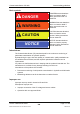
ContaminationSensor CS1000 General safety guidelines Basic symbols DANGER DANGER denotes situations which can lead to death if safety precautions are not observed. WARNING WARNING denotes situations which can lead to death if safety precautions are not observed. CAUTION CAUTION denotes situations which can lead to severe injuries if safety precautions are not observed. NOTICE NOTICE denotes situations which can lead to property damage if safety precautions are not observed.
ContaminationSensor CS1000 General safety guidelines Informal safety precautions In addition to the operating instructions, the general and local regulations on accident prevention and environmental protection are to be made available and observed. All safety guidelines and hazard warnings on the CS must be maintained in legible condition and replaced as required.
ContaminationSensor CS1000 General safety guidelines Training and instruction of personnel The CS may only be operated by properly trained and instructed personnel. Clearly determine which personnel are responsible for what. X Supervisor with the appropriate authority Individuals technical training X Electrician Instructed individuals Individuals Trainees may only use the CS when supervised by an experienced individual.
ContaminationSensor CS1000 New features — instruction modifications New features — instruction modifications The index is noted on the cover sheet of the operating and maintenance instructions and in the lower left corner after the part number on each page. Index "m" — from firmware version V 2.
ContaminationSensor CS1000 Interpreting the type label Interpreting the type label For ContaminationSensor identification details; see the type label. This is located on the top of the unit and contains the exact product description and the serial number. 1 6 30 C 000832 2 xxx 3 Row Definition 1 Model code CS1220-C-0-0-0-0/-000 2 Serial no. 3 Max. INLET press.: HYDAC Filtertechnik GmbH BeWa CS1000 3247149n en 2009-02-04.
ContaminationSensor CS1000 Checking the scope of delivery Checking the scope of delivery The ContaminationSensor CS1000 comes packed and factory-assembled, ready for operation. Before starting up the CS, check that the content of the package is complete. The following items are included: Qty 1 2 Designation ContaminationSensor, CS1000 Series (Model in acc. with the order - see type designation code).
ContaminationSensor CS1000 CS1000 Features CS1000 Features The CS1000 Series ContaminationSensor is a stationary measurement unit for the continuous monitoring of solid particle contamination in hydraulic and lubrication systems. The CS is designed to be used in low- or high-pressure hydraulic and lubrication circuits and test benches where a small amount of oil (between 30 ml/min and 300 ml/min) is diverted for measurement purposes.
ContaminationSensor CS1000 CS1000 Features 106,5 ca. 170 CS1x1x dimensions (without display) A 12 30 B ISO 228 83 G1/4 100 25 49,2 All dimensions in mm. A ca. 170 106,5 CS1x2x dimensions (with display) 12 30 B ISO 228 G1/4 83 25 102 54,2 All dimensions in mm. HYDAC Filtertechnik GmbH BeWa CS1000 3247149n en 2009-02-04.
ContaminationSensor CS1000 CS1000 Features Hydraulic connection types The direction of flow through the CS has to be from bottom to top. Use one port, A <-> B or D<->C as the INLET and the other port as the OUTLET. Pipe or hose connection (Type CS1xxx-x-x-x-x-0/-xxx) Hydraulic connection is done via ports A and B. Connection thread: G1/4 according to ISO 228 The direction of flow has to be from bottom (A) to top (B).
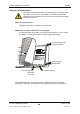
ContaminationSensor CS1000 CS1000 Features Fastening / mounting the CS1000 When attaching the CS make sure that the direction of flow is from bottom to top. Use the one (lower) port as the INLET and the other (upper) port as the OUTLET. When selecting the installation site, take ambient factors like the temperature, dust, water, etc. into account. The CS is designed for IP67 according to DIN 40050 / EN 60529 / IEC 529 / VDE 0470. Depending on the design, the CS1000 can be attached as follows: 1.
ContaminationSensor CS1000 CS1000 Features 3. Connecting plate or valve manifold mounting: using 4 cylindrical screws with an M6 hexagonal socket according to ISO4762. Display rotatable/Adjustable As Needed The CS1000 display can be continuously rotated by a total of 270°; 180° counterclockwise and 90° clockwise. To rotate the display, manually turn the cover plate required direction. Do not use tools to rotate the display. HYDAC Filtertechnik GmbH BeWa CS1000 3247149n en 2009-02-04.
ContaminationSensor CS1000 CS1000 Features CS1000 hydraulic installation The direction of flow through the CS has to be from bottom to top. Use one connection port as the INLET and the other as the OUTLET. Depending on your order, the CS features the following hydraulic connection types: (also see Chapter "Hydraulic connection types"): • Pipe/hose connection: The CS is connected to the hydraulic system via ports A and B using a pipe or hose.
ContaminationSensor CS1000 CS1000 Features Selecting the measurement point Proceed carefully when selecting a suitable measuring point in order to obtain cleanliness values that are continuous and coherent in real time. B B B A A A 2 1 1 2 3 1 INCORRECT INCORRECT OK The test point has to be selected so that the measured volume is taken from a turbulent flow area, e.g. a pipe bend. 2 The CS has to be installed in the vicinity of the test point in order to obtain precision-timed results.
ContaminationSensor CS1000 CS1000 Features Flow rate, differential pressure Δp and viscosity ν characteristics Differential pressure Δp and viscosity ν characteristics. All the values indicated in the figures below apply regardless whether the direction of flow is A->B or B->A. The permissible measured volumetric flow must be between 30 ml and 300 ml/min.
ContaminationSensor CS1000 CS1000 Features Hydraulic connection of the CS1000 NOTICE Working overpressure The CS will be destroyed. ► Observe the maximum operating pressure on the CS 1000 type label. Observe the following sequence when connecting the CS1000 to the hydraulic system: 1. First, connect the return line to the OUTLET port of the CS. Connection thread: G1/4 ISO 228, recommended diameter of line: ≥ 4 mm. 2. Now connect the other end of the return line to the system tank, for example. 3.
ContaminationSensor CS1000 CS1000 Features Electrical connection of the CS1000 Pin assignment Pin Assignment 1 Supply voltage 9 – 36 V DC 2 Analog output + 3 GND for supply voltage 4 GND for analog and switch outputs 5 HSI (HYDAC Sensor Interface) 6 RS485 + 7 RS485 - 8 Switching output (n.c.) The analog output is an active source of 4 - 20 mA or 0 - 10 V DC. The switch output is a passive n-switching Power MOSFET. The output switch is normally dead, closed.
ContaminationSensor CS1000 CS1000 Features Connection cable - Assignment / Color coding Our accessories list includes connection cables of various lengths with one connection plug (8-pole, M12x1, according to DIN VDE 0627) and an open end. HYDAC accessory cable color coding is listed in the table below.
ContaminationSensor CS1000 CS1000 Features Connecting cable ends - Examples 8 1 Schirm Shield Blindage 2 7 3 4 6 5 1 white 24 V DC = 3 green 6 pink RS-485 + 7 blue RS-485 - Converter RS-485 USB 5 grey HSI 2 brown SPS Eingang PLC Input SPS Entrée 250 4 yellow 5 V DC = 8 red Shield Circuit diagram: with two separate power supplies. (e.g.
ContaminationSensor CS1000 CS measurement modes CS measurement modes After powering up, the CS1000 automatically runs in the measuring mode that has been set.
ContaminationSensor CS1000 CS measurement modes Application: Stand-alone sensor Data output: Display & RS485 & analog output Purpose: Perform a single measurement and "stop" the result Function: Single measurement of solid contamination, without any switching functions When Single mode is selected in the Power Up menu, the display jumps directly to the following message after switching to the Measuring menu or after switching the CS on: START? The CS begins with individual measurement after the
ContaminationSensor CS1000 Operating the CS1000 per keyboard (Only CS1x2x) Operating the CS1000 per keyboard (Only CS1x2x) After the CS1000 is switched on, "HYDAC CS1000" is displayed in moving letters, then the firmware version is displayed for 2 seconds. This is followed by a countdown: WAIT99 to WAIT0. The duration of the countdown corresponds to the set measurement time (factory setting = 60 sec), which means that the countdown runs from 99 - 0 within the set measurement time.
ContaminationSensor CS1000 Operating the CS1000 per keyboard (Only CS1x2x) The keypad consists of six keys. These keys are used to operate the CS and to navigate through the menus (hierarchically structured). Keypad Description o.k.
ContaminationSensor CS1000 Operating the CS1000 per keyboard (Only CS1x2x) Measurement categories The measurement variables provide the user information about the cleanliness (or contamination) of the oil in his facility. The measurement variables are calibrated and indicate a measured value with an accuracy of +/- 1/2 ISO codes in the calibrated range.
ContaminationSensor CS1000 Operating the CS1000 per keyboard (Only CS1x2x) Service categories The service categories enable users to retrieve information on the current status in the ContaminationSensor. The service categories are not calibrated. They represent an approximate value for installing the sensor in the hydraulic system. Flow (flow rate) Display Description 120 Flow rate display (e.g.
ContaminationSensor CS1000 Operating the CS1000 per keyboard (Only CS1x2x) Activating/deactivating key lock The keypad can be locked to prevent entries. To enable or disable the key lock, press both keys simultaneously: Buttons Display (1 sec) Description + LOCK Key lock is enabled + UNLOCK Key lock is disabled The display returns to the default display after 1 second.
ContaminationSensor CS1000 Operating the CS1000 per keyboard (Only CS1x2x) DFAULT CANCEL SAVE CODE mTIME + Set measuring period 60 ADRESS Set bus address Reset to factory settings Discard changes and exit Save changes and exit For internal use only Description Set measuring period in seconds (10 – 300) + Description A Set address (a,b, ...
ContaminationSensor CS1000 Operating the CS1000 per keyboard (Only CS1x2x) Measuring Menu The Measuring menu allows you to change settings during operation. Selection To do Start Measuring menu Press Exit without saving Scroll to CANCEL and press Or automatically after 30 s without any action Exit and save changes Scroll to SAVE and press o.k. button. o.k. Measuring menu: o.k.
ContaminationSensor CS1000 Operating the CS1000 per keyboard (Only CS1x2x) ANA.OUT The measurement category selected here is output at the analog output (see also section 0) ANaOUT Select measurement category for analog output + SAeMAX SAE SAE+T TEMP HDaISO HDaSAE ISO 4 ISO 6 ISO 14 ISO ISO+T SAE A SAE B SAE C SAE D HYDAC Filtertechnik GmbH BeWa CS1000 3247149n en 2009-02-04.doc en Description SAE A-D SAE class A/B/C/D (coded) SAE class + temp.
ContaminationSensor CS1000 Operating the CS1000 per keyboard (Only CS1x2x) Measuring menu (CS13xx) The Measuring menu allows you to change settings during operation. Selection To do Start Measuring menu Press button Exit without saving Scroll to CANCEL and press Or automatically after 30 s without any action Exit menu and save changes Scroll to SAVE and press o.k. . o.k. Measuring menu: o.k.
ContaminationSensor CS1000 Operating the CS1000 per keyboard (Only CS1x2x) MODE – Configure measuring mode Setting the switching output selected in the Power Up menu. (Only the mode selected in the Power Up menu can be set here.) SWtOUT Set switching output o.k. M1 M2 M3 M4 SINGLE M1 Continuous measurement Description Continuous measurement Continuous measurement and switching Filter to cleanliness class and stop Filter to continuously monitor cleanliness class Start single measurement + stop o.k.
ContaminationSensor CS1000 Operating the CS1000 per keyboard (Only CS1x2x) UPPER M3 Filter to cleanliness class and stop + o.k. Description MEAsCH ISO NAS ISO code NAS class Target cleanliness class TARGET M4 Filter to continuously monitor cleanliness class + Description MEAsCH ISO NAS ISO code NAS class TARGET Target cleanliness class RSTART Resume filtration from this class CYCLE 60 SINGLE Start single measurement + stop Set test cycle time 1 - 1440 minutes o.k.
ContaminationSensor CS1000 Operating the CS1000 per keyboard (Only CS1x2x) ANA.OUT The measurement category selected here is output at the analog output (see Chapter 0) ANaOUT Select measurement category for analog output + NASMAX NAS NAS+T TEMP HDaISO HDaNAS ISO 2 ISO 5 ISO 15 ISO ISO+T NAS 2 NAS 5 NAS 15 NAS 25 HYDAC Filtertechnik GmbH BeWa CS1000 3247149n en 2009-02-04.doc en Description NAS maximum NAS class 2/5/15/25 (coded) NAS class+temp.
ContaminationSensor CS1000 Overview of menu structure Overview of menu structure Menu CS 12xx (ISO 4406:1999 and SAE) Power Up Menu Measuring mode (MODE) Mode „1“ (M1) Mode 2 (M2) Mode „3“ (M3) Mode „4“ (M4) Mode „Single“ (SINGLE) Measuring time (mTIME) Set value (60) Pump protection (pPRTCT) Set value (0) Bus address (ADRESS) HECOM3b address (HECOM) Set value (A) (IP) reserved for future use (MODBUS) reserved for future use Factory defaults (DFAULT) Cancel (CANCEL) Save changes, leave Power Up Menu (SAVE
ContaminationSensor CS1000 Overview of menu structure Analog output (ANaOUT) SAE A-D (SAeMAX) SAE class A/B/C/D (SAE) SAE class A/B/C/D + Temperature (SAE+T) Temperature (TEMP) HDA+ISO (HDaISO) HDA+SAE (HDaSAE) ISO-class 4µm (ISO 4) ISO-class 6µm (ISO 6) ISO-class 14µm (ISO 14) ISO Code (ISO) ISO Code + Temperature (ISO+T) SAE A (SAE A) SAE B (SAE B) SAE C (SAE C) SAE D (SAE D) Restart measurement, discard changes (CANCEL) Restart measurement, save changes (SAVE) Menu CS 13xx (ISO 4406:1987 and NAS) Powe
ContaminationSensor CS1000 Overview of menu structure Switching output (SWtOUT) Mode „1“ (M1) No settings necessary (NO SET) Mode 2 (M2) Switching point (SP1) Measuring channel (MEAsCH) NAS Maximum (NAsMAX) NAS (NAS) ISO-class 2µm (ISO 2) ISO-class 5µm (ISO 5) ISO-class 15µm (ISO 15) ISO Code (ISO) Temperature (TEMP) NAS-class 2 (NAS 2) NAS-class 5 (NAS 5) NAS-class 15 (NAS 15) NAS-class 25 (NAS 25) Switching function (SwFNCT) Beyond limit (BEYOND) Below limit (BELOW) Within band (WITHIN) Outside band (OU
ContaminationSensor CS1000 Using switching output Using switching output A description is provided below as to how the switch output behaves in the various modes and thus how it can be operated by the user. For a further description of the measurement modes, see also Chapter "CS Measurement modes".
ContaminationSensor CS1000 Using switching output Setting limit values The voltage supply to the CS1000 makes the switching output (SP1) conductive. This condition is maintained for the initial measurement period (WAIT period). Depending on the measurement mode, the switching output can be used as a Device ready function.
ContaminationSensor CS1000 Using switching output Within limits OUTSDE A value ≤ respective lower limit or a value ≥ respective upper limit Outside of limits OFF Becomes conductive again, when a value < respective lower limit or a value > respective upper limit After switching on or starting a test.
ContaminationSensor CS1000 Analog Output (ANAOUT) Analog Output (ANAOUT) Depending on CS model, the analog output is available as a 4 – 20 mA or 0 – 10 V signal. The CS model code allows you to detect the analog output. CS Model code Analog output CS 1 x x x - A – x – x – x – x /-xxx 4 - 20 mA CS 1 x x x - B – x – x – x – x /-xxx 0 – 10 V The electrical design of the analog output must have already been taken into consideration in the order.
ContaminationSensor CS1000 Analog Output (ANAOUT) SAE classes acc. to AS 4059 The following SAE values can be output via the analog output: • SAE A-D (SAEMAX) Only a single value is output. • SAE A / B / C / D All values are sequentially time-coded before output. • SAE A / SAE B / SAE C / SAE D Only one value is output. • SAE+T All values are sequentially time-coded before output. • HDA.SAE All values are sequentially time-coded before output.
ContaminationSensor CS1000 Analog Output (ANAOUT) Current I 19.2 mA < I < 19.8 mA 19.8 mA < I < 20 mA SAE class / error Not defined No measured value Voltage U 9.60 V < U < 9.90 V 9.90 V < U < 10 V If the contamination class is given acc. to SAE, the current I or voltage U can be calculated: I = 4.8 mA + SAE class x (19.2 mA - 4.8 mA) / 14 U = 2.4 V + SAE class x (9.6 V - 2.4 V) / 14 The SAE class can be calculated for a given current I or voltage U as follows: SAE class = (I - 4.8 mA) x (14/14.
ContaminationSensor CS1000 Analog Output (ANAOUT) SAE Klassen A / B / C / D (SAE) The SAE class A/B/C/D signal consists of 4 measured values transmitted with the following time-coded time slices: 1 3 1 7 5 I (mA) U (V) 20,0 19,8 19,7 19,5 19,2 4,8 10,0 9,9 9,85 9,75 High High Low Low 4,5 4,3 4,1 4,0 9,6 2,4 2,25 2,15 2,05 2,0 t (ms) 0,0 3000 300 4 2 Time Signal 6 8 Size Signal duration per pulse in ms Current (I) / Voltage (U) High / Low 1 Identifier SAE A 300 2 Measured
ContaminationSensor CS1000 Analog Output (ANAOUT) SAE A / SAE B / SAE C / SAE D (SAE A/SAE B/SAE C/SAE D) The SAE x setting enables the value of a class to be continuously output via the analog output.
ContaminationSensor CS1000 Analog Output (ANAOUT) HDA.SAE – Analog signal SAE to the HDA 5500 The HDA.SAE signal consists of 6 values (START / SAE A / SAE B / SAE C / SAE D / Status) which are output sequentially. Synchronization with the downstream control unit is a prerequisite.
ContaminationSensor CS1000 Analog Output (ANAOUT) HDA.SAE Signal 1/2/3/4 The current or voltage range is dependent on the contamination class according to SAE=0.0 – 14.0 (resolution 0.1 class). Current I I < 4.00 mA I = 4.00 mA I = 4.11 mA I = 4.23 mA ... I = 5.14 mA I = 6.29 mA I = 7.43 mA I = 8.57 mA I = 9.71 mA I = 10.86 mA I = 12.00 mA I = 13.14 mA I = 14.29 mA I = 15.43 mA I = 16.57 mA I = 17.71 mA I = 18.86 mA ... I = 19.77 mA I = 19.89 mA I = 20.00 mA SAE class / error Cable break SAE 0 SAE 0.
ContaminationSensor CS1000 Analog Output (ANAOUT) HDA Status Signal 5 The current or voltage of the output signal (5) is dependent on the status of the CS1000 as shown in the table below: Current I Status Voltage U I = 5.0 mA CS is functioning correctly U = 2.5 V I = 6.0 mA Device error / CS not ready U = 3.0 V I = 7.0 mA Flow insufficient (Flow 2 low) U = 3.5 V I = 8.0 mA SAE < 0 U = 4.0 V I = 9.0 mA No measured value (flow not defined) U = 4.5 V If the status signal is ≥ 6.0 mA or ≥ 3.
ContaminationSensor CS1000 Analog Output (ANAOUT) ISO Code acc. to 4406:1999 The following ISO values can be output via the analog output: • ISO 4 / ISO 6 / ISO 14 Only one value is output. • ISO-Code, 3-digit (>4 µm(c) / >6 µm(c) / >14 µm(c)) All values are sequentially time-coded before output. • ISO+T All values are sequentially time-coded before output. • HDA.ISO All values are sequentially time-coded before output.
ContaminationSensor CS1000 Analog Output (ANAOUT) Current I ISO contamination class / error I = 17.90 mA ISO 23 I = 18.47 mA ISO 24 I = 19.20 mA ISO 24.28 19.2 mA < I < 19.8 mA Not defined 19.8 mA < I < 20 mA No measured value Voltage U U = 8.95 V U = 9.24 V U = 9.60 V 9.60 V < U < 9.90 V 9.90 V < U < 10 V The current (I) or voltage (U) can be calculated for a given ISO contamination class as follows: I = 4.8 mA + ISO code x (19.2 mA - 4.8 mA) / 24.28 U = 2.4 V + ISO Code x (9.6 V - 2.4 V) / 24.
ContaminationSensor CS1000 Analog Output (ANAOUT) ISO 4 / ISO 6 / ISO 14 (ISO 4 / ISO 6 / ISO 14) The ISO x setting enables the value of a class to be continuously output via the analog output. ISO code (ISO), 3-digit The ISO code signal consists of 3 measured values (>4µm(c) / >6µm(c) / >14µm(c) ) and is time-coded with the following time slices.
ContaminationSensor CS1000 Analog Output (ANAOUT) ISO + T (ISO+T) The ISO+T signal consists of 4 measured values which are transmitted time-coded with the following time slices: 1 5 3 7 U (V) I (mA) 9,9 9,85 9,75 19,8 19,7 19,5 19,2 High 9,6 High 3000 3000 3000 4,8 Low 2,4 Low 2,15 2,05 2,0 4,3 4,1 4,0 0,0 time (ms) 300 2 4 Time Signal 6 8 Size Signal duration per pulse in ms Current (I) / Voltage (U) 1 Identifier > 4 µm(c) 300 High / Low 2 Measured value > 4 µm(c) 3000 C
ContaminationSensor CS1000 Analog Output (ANAOUT) HDA.SAE – Analog signal ISO to HDA 5500 The HDA.ISO signal consists of 6 measured values (START / ISO 6 / ISO 6 / ISO 14 / ISO 21 / Status) which are output sequentially. Synchronization with the downstream control unit is a prerequisite.
ContaminationSensor CS1000 Analog Output (ANAOUT) HDA.ISO Signal 1/2/3/4 The current 4 - -20 mA or voltage 2 - 10 V of the output signal is dependent on the ISO contamination class 0.0 - 24.4 (resolution 1 class) as shown in the table below: Current I I <4.00 mA I = 4.00 mA I = 4.39 mA I = 5.20 mA I = 5.92 mA I = 6.61 mA I = 7.28 mA I = 7.95 mA I = 8.63 mA I = 9.25 mA I = 9.91 mA I = 10.57 mA I = 11.23 mA I = 11.89 mA I = 12.55 mA I = 13.20 mA I = 13.86 mA I = 14.52 mA I = 15.20 mA I = 15.82 mA I = 16.
ContaminationSensor CS1000 Analog Output (ANAOUT) HDA Status Signal 5 The current or voltage of the output signal (5) is dependent on the status of the CS1000 as shown in the table below: Current I Status Voltage U I = 5.0 mA CS is functioning correctly U = 2.5 V I = 6.0 mA Device error / CS not ready U = 3.0 V I = 7.0 mA Flow insufficient (Flow 2 low) U = 3.5 V I = 8.0 mA ISO <9.<8.<7 U = 4.0 V I = 9.0 mA No measured value (flow not defined) U = 4.5 V If the status signal is ≥ 6.
ContaminationSensor CS1000 Analog Output (ANAOUT) ISO code signal acc. to 4406:1987 (CS 13xx only) The following ISO values can be output via the analog output: • ISO 2 / ISO 5 / ISO 15 Only one value is output. • ISO-Code, 3-digit (>2 µm / >5 µm / >15 µm) All values are sequentially time-coded before output. • ISO+T All values are sequentially time-coded before output. • HDA.ISO All values are sequentially time-coded before output.
ContaminationSensor CS1000 Analog Output (ANAOUT) Current I ISO contamination class / error I = 17.33 mA ISO 22 I = 17.90 mA ISO 23 I = 18.47 mA ISO 24 I = 19.20 mA ISO 24.28 19.2 mA < I < 19.8 mA Not defined 19.8 mA < I < 20 mA No measured value Voltage U U = 8.67 V U = 8.95 V U = 9.24 V U = 9.60 V 9.60 V < U < 9.90 V 9.90 V < U < 10 V The current (I) or voltage (U) can be calculated for a given ISO contamination class as follows: I = 4.8 mA + ISO code x (19.2 mA - 4.8 mA) / 24.28 U = 2.
ContaminationSensor CS1000 Analog Output (ANAOUT) ISO 2 / ISO 5 / ISO 15 (ISO 2 / ISO 5 / ISO 15) The ISO x setting enables the value of a class to be continuously output via the analog output. ISO code (ISO), 3-digit The ISO code signal consists of 3 measured values (>2 µm / >5 µm / >15 µm) which are copied time-coded as shown below.
ContaminationSensor CS1000 Analog Output (ANAOUT) ISO + T (ISO+T) The ISO+T signal consists of 4 measured values which are transmitted time-coded with the following time slices: 1 5 3 7 U (V) I (mA) 9,9 9,85 9,75 19,8 19,7 19,5 19,2 High 9,6 High 3000 3000 3000 4,8 Low 2,4 Low 2,15 2,05 2,0 4,3 4,1 4,0 0,0 time (ms) 300 2 4 Time Signal 6 Signal duration per pulse in ms Current (I) / Voltage (U) High / Low 1 Identifier > 2 µm 300 2 Measured value > 2 µm 3000 3 Identifier >
ContaminationSensor CS1000 Analog Output (ANAOUT) HDA.ISO – Analog signal ISO to HDA 5500 The HDA.ISO signal consists of 4 measured values (ISO 4 / ISO 6 / ISO 14 / ISO 21 / Status) which are output sequentially. Synchronization with the downstream control unit is a prerequisite.
ContaminationSensor CS1000 Analog Output (ANAOUT) HDA.ISO Signal 1/2/3/4 The current 4 - -20 mA or voltage 2 - 10 V of the output signal is dependent on the ISO contamination class 0.0 - 24.4 (resolution 1 class) as shown in the table below: Current I I < 4.00 mA I = 4.00 mA I = 4.39 mA I = 5.20 mA I = 5.92 mA I = 6.61 mA I = 7.28 mA I = 7.95 mA I = 8.63 mA I = 9.25 mA I = 9.91 mA I = 10.57 mA I = 11.23 mA I = 11.89 mA I = 12.55 mA I = 13.20 mA I = 13.86 mA I = 14.52 mA I = 15.20 mA I = 15.82 mA I = 16.
ContaminationSensor CS1000 Analog Output (ANAOUT) HDA Status Signal 5 The current or voltage of the output signal (5) is dependent on the status of the CS1000 as shown in the table below: Current I I = 5.0 mA I = 6.0 mA I = 7.0 mA I = 8.0 mA I = 9.0 mA Status CS is functioning correctly Device error / CS not ready Flow insufficient (Flow 2 low) ISO <9.<8.<7 No measured value (flow not defined) Voltage U U = 2.5 V U = 3.0 V U = 3.5 V U = 4.0 V U = 4.5 V If the status signal is ≥ 6.0 mA or ≥ 3.
ContaminationSensor CS1000 Analog Output (ANAOUT) NAS 1638 - National Aerospace Standard (Only CS 13xx) The following NAS values can be output via the analog output: • NAS Maximum (NAsMAX) Only one value is output. • NAS (2 / 5 / 15 / 25) All values are sequentially time-coded before output. • NAS 2 / NAS 5 / NAS 15 / NAS 25 Only one value is output. • NAS + T All values are sequentially time-coded before output. • HDA.NAS All values are sequentially time-coded before output.
ContaminationSensor CS1000 Analog Output (ANAOUT) Current I 19.2 mA < I < 19.8 mA 19.8 mA < I < 20 mA NAS class / error Not defined Voltage U 9.60 V < U < 9.90 V No measured value 9.90 V < U < 10 V The current (I) or voltage (U) can be calculated for a given NAS contamination class as follows: I = 4.8 mA + NAS class x (19.2 mA - 4.8 mA) / 14 U = 2.4 V + NAS class x (9.6 V - 2.4 V) / 14 The current I or voltage U can be calculated for a given NAS contamination class as follows: NAS class = (I - 4.
ContaminationSensor CS1000 Analog Output (ANAOUT) NAS classes (2 / 5 / 15 / 25) (NAS) NAS class signals 2 / 5 / 15 / 25 consist of 4 measured values transmitted with the following time-coded time slices: 1 3 1 7 5 I (mA) U (V) 20,0 19,8 19,7 19,5 19,2 4,8 10,0 9,9 9,85 9,75 High High Low Low 4,5 4,3 4,1 4,0 9,6 2,4 2,25 2,15 2,05 2,0 t (ms) 0,0 3000 300 4 2 Time Signal 6 8 Size Signal duration per pulse in ms Current (I) / Voltage (U) High / Low 1 Identifier 2 µm 300 2 M
ContaminationSensor CS1000 Analog Output (ANAOUT) NAS 2 / NAS 5 / NAS 15 / NAS 25 (NAS 2/NAS 5/NAS 15/NAS 25) The NAS x setting enables the value of a class to be continuously output via the analog output.
ContaminationSensor CS1000 Analog Output (ANAOUT) HDA.NAS – Analog Signal NAS to HDA 5500 The HDA.NAS signal consists of 4 measured values (Start / NAS 2 / NAS 5 / NAS 15 / NAS 25 / Status) which are output sequentially. Synchronization with the downstream control unit is a prerequisite.
ContaminationSensor CS1000 Analog Output (ANAOUT) HDA Signal 1/2/3/4 The current or voltage range is dependent on the contamination class according to NAS=0.0 – 14.0 (resolution 0.1 class). Current I I < 4.00 mA I = 4.00 mA I = 4.11 mA I = 4.23 mA ... I = 5.14 mA I = 6.29 mA I = 7.43 mA I = 8.57 mA I = 9.71 mA I = 10.86 mA I = 12.00 mA I = 13.14 mA I = 14.29 mA I = 15.43 mA I = 16.57 mA I = 17.71 mA I = 18.86 mA ... I = 19.77 mA I = 19.89 mA I = 20.00 mA NAS class / error Cable break NAS 0 NAS 0.1 NAS 0.
ContaminationSensor CS1000 Analog Output (ANAOUT) HDA Status Signal 5 The current or voltage of the output signal (5) is dependent on the status of the CS1000 as shown in the table below: Current I Status Voltage U I = 5.0 mA CS is functioning correctly U = 2.5 V I = 6.0 mA Device error / CS not ready U = 3.0 V I = 7.0 mA Flow insufficient (Flow 2 low) U = 3.5 V I = 8.0 mA NAS < 0 U = 4.0 V I = 9.0 mA No measured value (flow not defined) U = 4.5 V If the status signal is ≥ 6.0 mA or ≥ 3.
ContaminationSensor CS1000 Analog Output (ANAOUT) Fluid temperature (TEMP) The current range 4.8 - 19.2 mA or voltage range 2.4 - 9.6 V is dependent on the fluid temperature of from -25°C – +100°C (resolution: 1°C) or -13°F – 212°F (resolution: 1°F) Current I I < 4.00 mA 4.0 mA < I < 4.1 mA 4.1 mA < I < 4.3 mA 4.3 mA < I < 4.5 mA 4.5 mA < I < 4.8 mA I = 4.8 mA ... I = 7.68 mA I = 8.26 mA I = 8.83 mA I = 9.41 mA I = 9.98 mA I = 10.56 mA I = 11.14 mA I = 11.71 mA I = 12.29 mA I = 12.86 mA I = 13.
ContaminationSensor CS1000 Analog Output (ANAOUT) The current I or voltage U can be calculated for a given temperature as follows: I = 4.8 mA + (temperature [°C] + 25) x (19.2 mA - 4.8 mA) / 125 I = 4.8 mA + (temperature [°F] +13) x (19.2 mA - 4.8 mA) / 225 U = 2.4 V + (temperature [°C] + 25) x (9.6 V - 2.4 V) / 125 U = 2.4 V + (temperature [°F] + 13) x (9.6 V-2.4 V) / 225 The temperature in °C or °F can be calculated for a given current I or voltage U as follows: Temperature [°C]= ((I - 4.
ContaminationSensor CS1000 Status messages Status messages Status LED / display LED Blink code / Display / Analog output / Switch out Gree n Error No. Status To do CS o.k. --- The sensor is below its measurement range ISO 9/8/7 --- Status To do Flow insufficient Check that the flow is between 30 - 300 ml/min. Increase inlet pressure or reduce outlet pressure.
ContaminationSensor CS1000 LED Blink code / Display / Analog output / SwitchOut Status messages Status Error No.
ContaminationSensor CS1000 LED Blink code / Display / Analog output / SwitchOut Red Red Red Red Red 4.1 mA / 2.05 V* Open 4.1 mA / 2.05 V* Open 4.1 mA / 2.05 V* Open 4.1 mA / 2.05 V* Open HYDAC Filtertechnik GmbH BeWa CS1000 3247149n en 2009-02-04.doc Status messages CS 1000 Status To do Firmware error Reset (re-supply voltage) or contact HYDAC Error No.
ContaminationSensor CS1000 Status messages Analog output error signals If the CS enters into an error status all following measured value signals are output in a specific current strength (I) or voltage (U). Please refer to chapter "Error status" for the respective values for the current strength or voltage of the output signal during an error status). The time coding is preserved. Example: Error "Flow too low" (or "2 low") for the SAE output signal.
ContaminationSensor CS1000 Status messages Analog signal for HDA 5500 HDA status signal 5 table The current or voltage of the output signal (5) is dependent on the status of the CS1000 as shown in the table below: Current I Status Voltage U I = 5.0 mA CS is functioning correctly U = 2.5 V I = 6.0 mA Device error / CS not ready U = 3.0 V I = 7.0 mA Flow insufficient (Flow 2 low) U = 3.5 V I = 8.0 mA ISO <9.<8.<7 U = 4.0 V I = 9.0 mA No measured value (flow not defined) U = 4.
ContaminationSensor CS1000 Connecting CSI-D-5 (Condition Sensor Interface) Connecting CSI-D-5 (Condition Sensor Interface) The CSI-D-5 enables the operation from CS1000 via PC: • Setting parameters and limit values. • Reading out measurement data online. CSI-D-5 Connection overview Connect the CSI-D-5 according to the following diagram. CSI-D-5 USB-B PC PS2 CS 1000 ZBE 43-xx USB-A HYDAC Filtertechnik GmbH BeWa CS1000 3247149n en 2009-02-04.
ContaminationSensor CS1000 CS1000 in RS-485 bus CS1000 in RS-485 bus The CS1000 possesses an RS-485 interface which is to be used as a two-wire interface in half-duplex operation. The number of CS1000 per RS-485 bus is limited to 26 units because the HECOM bus is addressed with the letters A – Z. The length of the bus line and the size of the terminating resistance depend on the quality of cable used. The graphic below shows several CS1000 linked via the RS-485 interface and then connected to a PC. 2.
ContaminationSensor CS1000 Taking the CS1000 out of operation Taking the CS1000 out of operation Decommission according to the following steps: 1. Pull electric plug from CS. 2. Depressurize the hydraulic system. 3. Remove the connected hoses/piping from the CS. 4. The CS can now be removed. Disposing of CS1000 The packing material is to be disposed of as specified by law or national regulations or be reused.
ContaminationSensor CS1000 Spare parts and accessories Spare parts and accessories Description Pc. Part no. CD with: - PC software pack CoCoS 1000 and - Operation and maintenance instructions 1 3251484 ContaminationSensor Interface CSI-D-5 1 3249563 O-ring for flange connection (4.8x1.
ContaminationSensor CS1000 Cleanliness classes - brief overview Cleanliness classes - brief overview Cleanliness class - ISO 4406:1999 For ISO 4406:1999 particle counts are determined cumulatively, i.e. > 4 µm(c), >6 µm(c) and >14 µm(c) (manually by filtering the fluid through an analysis membrane or automatically using particle counters) and allocated to key figures. The goal of allocating particle counts to references is to facilitate the assessment of fluid cleanliness.
ContaminationSensor CS1000 Cleanliness classes - brief overview Note that increasing the key figure by 1 causes the particle count to double. Example: ISO code 18 / 15 / 11 means: Cleanliness class No. particles / ml Size ranges 18 1,300 – 2,500 > 4 µm (c) 15 160 – 320 > 6 µm (c) 11 10 – 20 Are found in 1 ml of the analyzed sample > 14 µm (c) Overview of modifications - ISO4406:1987 vs.
ContaminationSensor CS1000 Cleanliness classes - brief overview Cleanliness class - SAE AS 4059 Like ISO 4406, SAE AS 4059 describes particle concentrations in liquids. The analysis procedures can be applied in the same manner as ISO 4406:1999. An additional feature in common with ISO 4406:1999 is that cleanliness classes are grouped on the basis of cumulative number of particles (i.e. all particles that are larger than a certain limit value are > 4 µm, for example).
ContaminationSensor CS1000 Cleanliness classes - brief overview Definition acc. to SAE Particle count (absolute) larger than a defined particle size Example: Cleanliness class according to AS 4059= 6 The maximum permissible number of particles in the individual size ranges is shown in the table in bold. Cleanliness class according to AS 4059= 6 B Size B particles may not exceed the maximum number shown for class 6 6 B = max.
ContaminationSensor CS1000 Cleanliness classes - brief overview Cleanliness Class - NAS 1638 Like ISO 4406, NAS 1638 describes particle concentrations in liquids. The analysis methods can be applied in the same manner as ISO 4406:1999. As opposed to ISO 4406, certain particle ranges are counted in NAS 1638 and assigned to key figures. The following table shows the cleanliness classes depending on determined particle concentration. Cleanliness class 2..5 µm Maximum particle concentration / 100 ml 5..
ContaminationSensor CS1000 Checking/resetting factory default settings Checking/resetting factory default settings Power Up menu Power Up Menu Value MODE M.TIME pPRTCT ADRESS CALIB M1 60 0 HECOM NAS Mode Value MODE MODE MODE M2 M2 M2 MODE MODE MODE MODE MODE MODE MODE M2 M3 M3 M4 M4 M4 M4 A (CS 13xx, only) RELAY1 RELAY1 RELAY1 MEAS.CH SAeMAX SW.FNCT BEYOND LIMITS LOWER 2012-0717 RELAY1 LIMITS UPPER 21.1=.16 MEAsCH ISO TARGET 17.15.12 MEAsCH ISO TARGET 17.15.12 RESTART 21.19.
ContaminationSensor CS1000 Technical data Technical data General data Mounting position Any (recommended: vertical position) Self-diagnosis Continuously with error display via status LED and display Display (only CS 1x2x) LED, 6 digits, in 17 segment format Measurement categories CS 12xx CS 13xx Service categories Flow Out Drive Temp Ambient temperature range -30° ... +80° C / -22° ... 176° F Storage temperature range -40° ... +80° C / -40° ... 176° F Relative humidity Max.
ContaminationSensor CS1000 Recalibration Recalibration We recommend recalibrating the sensor every 2 – 3 years. Customer service For recalibration and repair work use the follow shipping address: HYDAC Service GmbH Product Support, Werk 7 Rehgrabenstrasse 3 66125 Saarbruecken / Dudweiler - Germany Telephone: ++49 (0) 6897 509 – 883 HYDAC Filtertechnik GmbH BeWa CS1000 3247149n en 2009-02-04.
ContaminationSensor CS1000 Model code Model code CS 1 0 0 0 - A - 0 - 0 - 0 - 0 /- 000 Product CS = ContamionationSensor Series 1= 1000 Series Contamination code 2= ISO4406:1999; SAE AS4059 (D) 3= ISO4406:1987; NAS 1638 ISO4406:1999; SAE AS4059 (D) Options 1= without display 2= with display, continuously variable rotation by 270° Fluids 0= petroleum-based 1= for phosphate esters Analog interfaces A= 4 ... 20 mA B= 0 ...
Notes
Notes
Notes
HYDAC Filtertechnik GmbH Service Technology / Filter Systems Division Industriegebiet Postfach 1251 66280 Sulzbach / Saar 66273 Sulzbach / Saar Germany Germany Phone: +49 (0) 6897 509 01 Fax: +49 (0) 6897 509 846 Fax: +49 (0) 6897 509 577 Internet: www.hydac.com E-mail: filtersysteme@hydac.