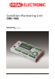
Condition Monitoring Unit CMU 1000 User manual (Translation of original manual) Revised 17.12.2009 HYDAC ELECTRONIC GMBH Mat.-No.
Condition Monitoring Unit CMU 1000 Revised 17.12.2009 HYDAC ELECTRONIC GMBH Page 2 Mat.-No.
Condition Monitoring Unit CMU 1000 Page 3 Table of Contents 1 2 3 General...........................................................................................................................9 1.1 Previous Knowledge..............................................................................................9 1.2 Structure of the Manual.........................................................................................9 1.3 Copyright Protection ...........................................
Condition Monitoring Unit CMU 1000 Page 4 5.2.3 Modem Connection.........................................................................................37 5.2.3.1 Device Connection/Pin Connections...........................................................37 5.2.3.2 Establishing Connection with GSM Radio Module CSI-F-10 ......................38 5.2.3.3 Connection Setup with CMU 1000 using GSM Mobile Network..................42 5.2.4 TCP Connection ..........................................................
Condition Monitoring Unit CMU 1000 Page 5 7.2 Data Sources ........................................................................................................81 7.2.1 Numerical Constant ........................................................................................81 7.2.2 Measured Value..............................................................................................81 7.2.3 Digital Input............................................................................................
Condition Monitoring Unit CMU 1000 7.6.7 7.6.8 Page 6 Within..............................................................................................................99 Outside ...........................................................................................................99 7.7 Boolean Links ....................................................................................................100 7.7.1 Not .....................................................................................
Condition Monitoring Unit CMU 1000 8.3.3 Page 7 Lower Measured Value Limit Greater than Upper Measurement Value Limit114 8.4 Error Messages with Result Values/Actions ...................................................114 8.4.1 Invalid Output LED Selected.........................................................................114 8.4.2 Duplicate Usage of Output LED....................................................................114 8.4.3 Invalid Digital Output.........................................
Condition Monitoring Unit CMU 1000 Page 8 Preface We have compiled the most important instructions for the operation and maintenance of our product for you, its user, in this documentation. It will acquaint you with the product and assist you in using it as intended in an optimal manner. Keep it in the vicinity of the product so it is always available. Note that the information on the unit's engineering contained in the documentation was that available at the time of publication.
Condition Monitoring Unit CMU 1000 Page 9 1 General This manual is a constituent part of the device. It contains texts and graphics concerning the correct handling of the product and must be read before installation, assembly and the operation of the device. The manual offers information concerning the safe operation of as well as the installation and programming of the Condition Monitoring Unit CMU 1000.
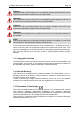
Condition Monitoring Unit CMU 1000 Page 10 Danger! means that death, severe bodily injury or considerable property damage will occur if the respective precautionary measures are not implemented. Warning! means that death, severe bodily injury or considerable property damage could occur if the respective precautionary measures are not implemented. Caution! means that some non-severe bodily injury or property damage could occur if the respective precautionary measures are not implemented.
Condition Monitoring Unit CMU 1000 Page 11 2 Safety 2.1 General Safety Precautions Follow the specifications contained in this description. Non-observance of the instructions, operation outside of the following intended utilization, incorrect installation/assembly or erroneous handling of the product can lead to severe impairments with respect to the safety of personnel and systems/machines and result in the revocation of warranty and liability claims.
Condition Monitoring Unit CMU 1000 Page 12 2.2 Proper/Designated Use The CMU1000 is an electronic evaluation unit designed for permanent machinery and systems condition monitoring. The device must be supplied for this purpose with machine data that is gathered through the connected sensors. The recorded data (whether processed or unprocessed) can be forwarded by the CMU 1000 through various interfaces to other units and/or monitoring levels.
Condition Monitoring Unit CMU 1000 Page 13 3 Setup and Function The CMU1000 is an electronic device for regular (permanent) status monitoring of hydraulic systems or machinery. This procedure is also referred to as "Condition Monitoring". 3.1 Hardware Setup In order to fulfill the aforementioned task, the CMU 1000 must be supplied with relevant machinery and/or systems data, which it receives through connected sensors.
Condition Monitoring Unit CMU 1000 Page 14 3.3 Terminal Allocations Plugs Pin Channel Function I/O 1 2 K C IN IN / OUT 3 4 5 6 J B 7 8 9 10 I A Analog input K HSI Channel C / Sensor recognition input K GND Power supply Analog input J HSI Channel B / Sensor recognition input J GND Power supply Analog input I HSI Channel A / Sensor recognition input I GND Power supply X1 11 12 1 2 N F 3 4 5 6 M E 7 8 9 10 L D X2 11 12 X3 1 2 3 4 5 6 P H 7 8 9 10 O G 11 12 Revised 17.12.
Condition Monitoring Unit CMU 1000 Plugs Pin X4 1 2 3 4 5 6 7 8 9 10 11 12 X5 1 2 3 4 5 6 7 8 9 10 11 12 X6 1 2 3 4 5 6 7 8 9 10 11 12 Revised 17.12.
Condition Monitoring Unit CMU 1000 Page 16 3.4 Examples of Connections 3.4.1 SMART sensors HLB 1000 HLB 1000 +UB GND HSI 1 2 3 4 5 +UB GND HSI 1 2 3 4 5 1 2 3 4 5 ZBE 26 Sensor recognition + Signal 12 11 10 9 +UB GND HSI Ana. A I A B 1 2 3 4 5 1 2 3 4 5 12 11 10 9 +UB GND HSI Ana. A I External power supply: 10..
Condition Monitoring Unit CMU 1000 Page 17 3.4.2 Standard HSI Sensors HDA xxxx-H ETS xxxx-H EVS xxxx-H +UB Gnd Adr HSI Sig 1 4 2 5 3 Signal Sensor recognition 12 11 10 9 8 7 6 5 4 3 2 1 +UB GND HSI Ana. +UB GND HSI Ana. +UB GND HSI Ana. A I B J C K -X1 3.4.3 Standard Analog Sensors HDA xxxx ETS xxxx EVS xxxx ENS xxxx HDA xxxx ETS xxxx EVS xxxx ENS xxxx Two-wire line Signal + Signal - Three-wire line +UB GND Signal 12 11 10 9 8 7 6 5 4 3 2 1 +UB GND HSI Ana. +UB GND HSI Ana. +UB GND HSI Ana.
Condition Monitoring Unit CMU 1000 Page 18 3.4.5 GSM Module CSI-F-10 CSI-F-10 18..35 V DC / 3,5 A HSI +UB GND 5 4 1 2 3 1 2 3 4 5 6 7 HSI RS232 RS232 IOLink IOLink IOLink VDC Master TxD RxD L+ C/Q GND IN 8 9 10 11 12 VDC IN VDC GND VDC GND VDC GND VDC GND -X5 Revised 17.12.2009 HYDAC ELECTRONIC GMBH Mat.-No.
Condition Monitoring Unit CMU 1000 Page 19 4 Installation and Initial Operation 4.1 Installation Guidelines We recommend the installation of the CMU 1000 in a control cabinet or switchbox. It can be mounted on a standard top hat rail either horizontally or vertically.
Condition Monitoring Unit CMU 1000 Page 20 4.2 Control Element on the Device The following control element is available on the device for operating the CMU 1000 and performing the basic settings: Keypad LCD display 4.3 Power Supply Connection Before installing or removing an electrical device, you must make sure that the voltage supply to the devices is switched off.
Condition Monitoring Unit CMU 1000 Page 21 4.4 Behavior when Switching On/Restart The CMU 1000 is not equipped with a power switch. The behavior of the device following switch-on depends on whether or not a CM Program has been stored in the device memory. 4.4.
Condition Monitoring Unit CMU 1000 Page 22 If one or more output values are programmed in the CM Program that is loaded, (see Chap. 7.9.1 and 7.9.2), then the display will jump to the first output value after startup. When several output values have been programmed, you can switch between the individual program values with the ▲ and ▼ key. Example: Oil temp. tank 31.2°C ▲ ▼ Working pressure 27 bars Note! No conditions are registered or saved in the device after switch-off.
Condition Monitoring Unit CMU 1000 Page 23 5 Basic Settings/Menu Structure The CMU 1000 configuration and settings can be carried out in two different modes: 5.1 Configuration on the Device 5.1.1 Menu Structure for Operation on the Device Level 1 Input values Level 2 Level 3 Sensor A [Display of current measured value] [Display of current measured value] Sensor B : : Sensor R Level 4 Language Port Dateformat [Enter name] German English French RS 232 / HSI TT.MM.
Condition Monitoring Unit CMU 1000 Level 1 Level 2 Level 3 Page 24 Level 4 Channel I : Channel P Level 5 Level 6 High range [Enter value] 0 0.0 0.00 0.00 [Enter unit] [Enter name] Off Active [Enter value] [Enter value] 0 0.0 0.00 0.
Condition Monitoring Unit CMU 1000 Page 25 5.2 Configuration Using CMWIN PC Software The configuration of the CMU 1000 and the carrying out of the basic settings can also be performed from a PC with the "CM Manager". The "CM Manager" is a component part of the CMWIN HYDAC PC software, starting with Version 3, and provides you with various tools and functions for the connecting, configuring, parameterizing and reading-out of CM devices.
Condition Monitoring Unit CMU 1000 Page 26 • • Mark the option "Direct Connection" option in the window that opens. Click on "Change" to open the window for the interface settings. • Make the corresponding preselection for the port settings in the window that opens under Interface selection. Select the respective port address and Baud rate under Interface settings. As an alternative, you can also search automatically under CM device search for CM devices connected to the PC by pressing "Start".
Condition Monitoring Unit CMU 1000 Page 27 • In the Interface field, select the option "Open" in order to open the selected interface (COM port). The opened interface will be symbolized by a green dot on the right-hand edge of the window. • Afterwards click on "Connect" in the Sensor field to connect the CMU 1000 to the PC. The successful connection will be symbolized by a green dot on the right-hand edge of the window. Revised 17.12.2009 HYDAC ELECTRONIC GMBH Mat.-No.
Condition Monitoring Unit CMU 1000 • • • • • Page 28 Pressing "Disconnect" in the Device field allows you to interrupt the existing connection between the CMU 1000 and the PC. The interface (COM port) used can be closed again on the PC by pressing "Close" in the Interface field. At the end you also have the option of selecting an automatic connection setup.
Condition Monitoring Unit CMU 1000 Page 29 5.2.2 Direct Connection via HSI Bus You can connect several HYDAC CM devices with one another (maximum of 26 devices) via the so-called "HSI Bus". Each CM device must be assigned an HSI Bus address for this purpose (see Chap. 5.2.5.7). This kind of bus setup is presented below, using as an example three CMU 1000 devices. Other HYDAC CM devices such as SMART sensors (e.g.
Condition Monitoring Unit CMU 1000 Page 30 5.2.2.2 Connection Setup via CSI-B-2 Interface Module • • Start the HYDAC PC software CMWIN In the Units Menu, select the "CM Manager" option. • If the Connection window does not open automatically, "Connection" in the menu bar of the CM Manager. Mark the option "Direct Connection" option in the window that opens. Click on "Change" to open the window for the interface settings.
Condition Monitoring Unit CMU 1000 Page 31 • Select Change in the Bus address line. The following window opens: • • Select the respective device address in the selection window (Address d in our example). Confirm this with OK. • Afterwards click on Connect to connect the PC to the CMU 1000 (Address d). • The successful establishment of the connection will be signalled as shown below: • End the connection setup by confirming with OK. Revised 17.12.2009 HYDAC ELECTRONIC GMBH Mat.-No.
Condition Monitoring Unit CMU 1000 Page 32 5.2.2.3 Device Connection without CSI-B-2 Interface Module As an alternative, you can also set up an HSI Bus without a CSI-B-2 interface module and access the individual devices from the PC. For this you will need a CMU 1000 for communications with the PC, which in such cases functions as an "HSI Master". • • • First establish which CMU 1000 is the "Master" for the HSI Bus, i.e. at which CMU 1000 the PC will be connected.
Condition Monitoring Unit CMU 1000 • • • • • • • Page 33 If the Connection window does not open automatically, "Connection" in the menu bar of the CM Manager. Mark the option "Direct Connection" option in the window that opens. Click on "Change" to open the window for the interface settings. select Make the corresponding preselection for the port settings in the window that opens under Interface selection.
Condition Monitoring Unit CMU 1000 Page 34 • To set up a connection with one "Slave" CMU (e.g. Address d), proceed as follows: • Select Change in the Pass-through mode line. The following window opens: • Select the HSI channel in the selection window to which the slave devices are connected (in our example, Port H at the "Master" CMU). Afterwards, click on Switch on in order to switch on the pass-through mode for the selected channel. • • The following message appears: • Confirm this with OK.
Condition Monitoring Unit CMU 1000 Page 35 • Select Change in the Bus address line. The following window opens: • • Select the respective device (Address d in our example). Confirm this with OK. • Afterwards click on Connect to connect the PC to the Slave CMU (Address d). • The successful establishment of the connection will be signalled as shown below: • End the connection setup by confirming with OK. Revised 17.12.2009 address HYDAC ELECTRONIC GMBH in the selection window Mat.-No.
Condition Monitoring Unit CMU 1000 • Page 36 The following message now appears in the Master CMU display: Pass-through Mode ESC to Finish The message will remain in the display for as long as the "Master" CMU continues to be operated in pass-through mode. The pass-through mode can also be switched off on the CMU itself (instead of by means of the Connection Menu in the CM Manager) by pressing the Esc key on the device.
Condition Monitoring Unit CMU 1000 Page 37 5.2.3 Modem Connection You also have the option of setting up a connection by means of the Standard GSM mobile radio network. In the following we present an example of this kind of communication link. 5.2.3.1 Device Connection/Pin Connections Connect a Standard GSM modem to your PC and connect the CMU 1000 to the HYDAC GSM radio module CSI-F-10 in accordance with the diagram. Example: GSM 5 4 3 2 15 4 3 2 1 +UB GND HSI 18..
Condition Monitoring Unit CMU 1000 Page 38 5.2.3.2 Establishing Connection with GSM Radio Module CSI-F-10 • Connect the CMU 1000 for configuring the CSI-F-10 GSM radio module to your PC as also described in Chapter 5.2.1 Direct Connection, Chapter 5.2.2 Direct Connection via HSI Bus or Chapter 5.2.4 TCP Connection. • • Start the HYDAC PC software CMWIN In the Units Menu, select the "CM Manager" option. • If the Connection window does not open "Connection" in the menu bar of the CM Manager.
Condition Monitoring Unit CMU 1000 Page 39 • The following message appears: • Select "Change" in the Bus address line. The following window opens: • In the selection window, select "Busmaster" and then click on OK to apply the address. • Then click on "Connect" to connect the PC to the CSI-F-10 GSM radio module (address busmaster). Revised 17.12.2009 HYDAC ELECTRONIC GMBH Mat.-No.
Condition Monitoring Unit CMU 1000 Page 40 • Successful establishment of the connection will be signaled as shown below: • End the connection setup by confirming with OK. • In the CM Manager under Actions / Performing a Dialog / Permissions, open the following input window and input the mobile phone number authorized for accessing the CMU 1000.
Condition Monitoring Unit CMU 1000 Page 41 • Click on "Disconnect" under Connection in the Device box to break the existing connection with the CSI-F-10. • The following window opens: • Then click on "Yes" to reactivate the busmaster again. Revised 17.12.2009 HYDAC ELECTRONIC GMBH Mat.-No.
Condition Monitoring Unit CMU 1000 Page 42 5.2.3.3 Connection Setup with CMU 1000 using GSM Mobile Network • • Start the HYDAC PC software CMWIN In the Units Menu, select the "CM Manager" option. • If the Connection window does not open automatically, "Connection" in the menu bar of the CM Manager. Mark the "Modem Connection" option in the window that opens. Click on "Change" to open the window for the interface settings.
Condition Monitoring Unit CMU 1000 Page 43 • • You can set up a list of telephone numbers (address book) with Telephone list. Click on “OK“ to apply the entries or “Cancel“ to discard these changes. In either case you will then return to the Connection window. • Click on Open to open the selected interface. The opened interface is indicated by a green dot on the upper right. Click on "Change" to open the window for the pass-through mode.
Condition Monitoring Unit CMU 1000 Page 44 • The following message appears: • Confirm this with OK. • Afterwards click on Connect to connect the PC to the CMU 1000 that is connected with the CSI-F-10 • The successful establishment of the connection will be signalled as shown below: • End the connection setup by confirming with OK. Revised 17.12.2009 HYDAC ELECTRONIC GMBH Mat.-No.
Condition Monitoring Unit CMU 1000 Page 45 5.2.4 TCP Connection As a third option, you can set up a link between the PC and the CMU 1000 by means of an Ethernet network. In the following we present an example of this kind of link. 5.2.4.1 Device Connection Use one Standard RJ45 cable each to connect your PC and the CMU 1000 to a shared Ethernet network. Note! In order to be able to set up a connection via Ethernet, the network settings and parameters in the CMU 1000 must first be correctly stored.
Condition Monitoring Unit CMU 1000 Page 46 • • • Enter the IP Address stored in the network settings of the CMU 1000. You can set up a list of addresses (address book) with Address list. With Connection test you can test the link from the PC to the CMU 1000. If the IP Address has been entered correctly, then the following message will appear: • Click on “OK“ to apply the entries or “Cancel“ to discard these changes. In either case you will then return to the Connection window.
Condition Monitoring Unit CMU 1000 • Page 47 End the connection setup by confirming with OK. Revised 17.12.2009 HYDAC ELECTRONIC GMBH Mat.-No.
Condition Monitoring Unit CMU 1000 Page 48 5.2.5 Actions 5.2.5.1 Display Device Status • Status The "Status" indicates the current condition of the device. The individual conditions can be be specified in greater detail via the following table. Ready Stand-By No active error present, device is ready for operation No active error present, but device is currently not ready for operation; it may be that individual device functions are switched off or the device is in a startup phase, etc.
Condition Monitoring Unit CMU 1000 Page 49 5.2.5.2 Display Device Information • Here the values of the following status parameters are displayed: - Part numer - Serial number - Channel information The Channel information reflects the numerical input values from the CM Program. Channel 0 corresponds thereby to the first numerical input value in the CM Program, Channel 1 the second one, etc.
Condition Monitoring Unit CMU 1000 Page 50 5.2.5.4 Managing Recordings • Here you can manage the recordings (copying, opening, updating, deleting) stored in the CMU 1000 You have the following options for saving and copying: 5.2.5.5 Performing a Dialog This menu option corresponds to the menu option "Settings" in the internal device structure for the purpose of configuring the CMU 1000. The following settings can be made: Base settings • • • • Name Port Language Dateformat Revised 17.12.
Condition Monitoring Unit CMU 1000 Page 51 Recording settings Here you specify whether you wish the recorded data held in the internal memory to be deleted after copying onto a USB stick and whether, after the CMU reboots, to generate a new record file or to continue with the previous one. • • Delete recordings after copy Continue recording [ [ yes / yes / no] no] HLB reset Here you can reset an HLB connected to Channel A .. H (delete memory). • • HLB Reset Sensor [ yes / no] [Select sensor A ..
Condition Monitoring Unit CMU 1000 Page 52 Network settings If the CMU 1000 is integrated in a network at the customer site, then the following settings need to be carried out in accordance with this network: • • • • IP Address Subnetwork mask Gateway Address MAC Address [enter IP Address] [enter Subnetwork mask] [enter Gateway Address] [permanently set at the factory, read-only] Example: Peripherals - Channel Settings • Channel A to Channel H (HSI channels) - Name [Enter name] Revised 17.12.
Condition Monitoring Unit CMU 1000 • Channel I to Channel P - Name - Mode - Input signal *) - Low range - High range - Decimal format - Unit Page 53 [Enter name] [Off / Manual / Autodetect] [HSI / 0..20 mA / 4..20 mA / 0..5 V / 0..10 V / 0.5..4.5 V / 0..50 V / 0.5..5.5 V / 1..5 V / 1..6 V / -10..+10 V] [Enter low range] [Enter high range] [0 / 0.0 / 0.00 / 0.
Condition Monitoring Unit CMU 1000 • Page 54 PWM 1, PWM 2 (Analog output 1, Analog output 2) You use the PWM settings to establish which type of signal is to be available at the two analog ouputs. Revised 17.12.2009 HYDAC ELECTRONIC GMBH Mat.-No.
Condition Monitoring Unit CMU 1000 Page 55 5.2.5.6 Managing Configurations Here you can generate and manage various configuration files. These configuration files can, for example, be generated in series on a "Master" CMU and then subsequently loaded onto an unlimited number of other CMUs.
Condition Monitoring Unit CMU 1000 Page 56 - With Load you can transfer a configuration file (marked in the lower display field) from the PC to the CMU 1000. The following message appears after the completion of the transfer: All of the settings stored in the configuration file were carried out after the transfer of the file in the CMU 1000. - When you press Save, you generate a new configuration file or save a modified one to the previously specified target folder (in our example: C:\Temp).
Condition Monitoring Unit CMU 1000 Page 57 • Settings The basic settings and the network settings are stored in the Settings Configuration file. • Sensor configuration The peripherals settings are stored in the Sensor Configuration file. Revised 17.12.2009 HYDAC ELECTRONIC GMBH Mat.-No.
Condition Monitoring Unit CMU 1000 • Page 58 Input configuration The values of the numerical and Boolean input values used in the CM Program are stored in the input configuration file. 5.2.5.7 Set bus address Here you can assign the CMU 1000 an "HSI Bus address". This is required when several CMU 1000 (or other HYDAC CM devices) are connected to one HSI Bus and these devices are all set up to be be addressed by a central PC. A total of a maximum of 26 HYDAC CM devices can be linked to one HSI Bus, i.e.
Condition Monitoring Unit CMU 1000 Page 59 5.2.5.8 Managing Sensor Constellations Reliable system monitoring means ensuring that exactly the same sensors that were connected at the time the CMU 1000 was configured are connected during operation. The sensor constellation is used for this purpose. The sensor constellation is a monitoring instrument for the connected sensor system, i.e. it performs a continuous comparison between the connected "Actual" sensor system and the specified "Nominal" sensor system.
Condition Monitoring Unit CMU 1000 Page 60 5.2.5.9 Display Input Values • Here the current measured values and statuses of the analog (also HSI and SMART) and digital sensors connected to the CMU 1000 are displayed Revised 17.12.2009 HYDAC ELECTRONIC GMBH Mat.-No.
Condition Monitoring Unit CMU 1000 Page 61 5.2.6 Extras 5.2.6.1 Update Firmware Caution The voltage supply to the CMU 1000 is not permitted to be interrupted during the firmware update. If the voltage supply fails during the update process, then troublefree functioning can no longer be ensured and the device must be sent back to HYDAC SERVICE GMBH. • You can update the firmware of your CMU 1000 after selecting this menu option.
Condition Monitoring Unit CMU 1000 Page 62 • Confirming with Continue will cause the data to be transferred to the CMU 1000. • Confirming with Continue will cause the data in the CMU 1000 to be checked, and then the two following windows will appear one after the other: Revised 17.12.2009 HYDAC ELECTRONIC GMBH Mat.-No.
Condition Monitoring Unit CMU 1000 • Page 63 Confirming again with Continue will activate the new firmware in the device. The following messages will appear one after the other in the CMU 1000 display for this purpose for approximately 10 seconds: Sub CPU Update Don't turn off Main CPU update Don't turn off Afterwards, the CMU 1000 reboots with the updated firmware. • The following window opens as the last one in the sequence in the CMWIN. Pressing Close returns you to the CM Manager.
Condition Monitoring Unit CMU 1000 Page 64 5.2.6.2 Set Password Protection • To prevent unauthorized access to the CMU 1000, you can equip the device with password protection. Select the function Set password protection for this purpose. The following window opens: You are prompted at this point to enter a password. If the CMU 1000 is still in the condition it was at the time of delivery or if no password protection has been set, then the standard password for this function is: 0000.
Condition Monitoring Unit CMU 1000 Page 65 5.2.6.3 Change Password • Here you have the opportunity of changing the password. After the Change passwort function has been selected, the following window opens: - Enter the previous password in the top line. Enter the new password in the middle line. Repeat the new password in the bottom line. Confirm the action with OK (the new password is immediately activated) or end the action by clicking on Cancel without changing the password. 5.2.6.
Condition Monitoring Unit CMU 1000 Page 66 6 CM Editor The CMU 1000 processes your program in continuous cycles. You generate the program with the CM Editor and load it afterwards into the CMU 1000. The CM Editor is a constituent part of the HYDAC PC software CMWIN starting with Version 3 and provides you with various tools and functions for designing, integrating and testing your CM program.
Condition Monitoring Unit CMU 1000 Page 67 6.1 Menu Bar The menu bar of the CM Editor is tailored to the MS Windows user interface and contains the following menu structure: 6.1.1 File • With "New", you can establish for which platform (CM device) the CM program is to be created before beginning the actual creation of the CM program.
Condition Monitoring Unit CMU 1000 Page 68 6.1.2 CM Program • After "Display" is selected, a window opens in which all of the functions used in the currently opened CM program will be listed, together with inscriptions and parameters. The list can be printed out by selecting "Print". Pressing "Close“ takes you back to the CM Editor. • With "Simulate", you can simulate and/or test the CM program that is currently open. The Simulation window opens for this purpose.
Condition Monitoring Unit CMU 1000 Page 69 With "Perform cycle", you can start the simulation for a single processing cycle and then view the thereby resulting status modifications of the actions afterwards. With "Start autom. cycle“, you start a permanent, continuous program simulation. You can change the input values during the simulation any way you like and observe the status modifications of the actions. Mit "End autom. cycle“, you stop the permanent, continuous program simulation.
Condition Monitoring Unit CMU 1000 • Page 70 You can transfer the currently opened CM program to the CMU 1000 with "Transfer into device“. Note! Only error-free programs can be transferred into the CMU 1000. The following message appears after the program has been successfully applied: Here you can select whether you also wish to transfer the source code of the program into the CMU 1000.
Condition Monitoring Unit CMU 1000 Page 71 • You can transfer and then edit the CM program currently available in the CMU to your PC with "Receive from device". This will however only work if the CM program source code from the original creator has also been transferred into the CMU 1000.
Condition Monitoring Unit CMU 1000 Page 72 6.1.3 Grouping • With Create grouping you can join several functions to make an interconnected unit and transfer and copy these as a block. First mark the functions to be grouped by enclosing them in a frame created with the help of the cursor. Afterwards, select “Group“ in the menu bar and then “Create grouping“ in the drop-down menu that appears. • Pressing “Cancel grouping“ releases the functions linked together in the group from one another again.
Condition Monitoring Unit CMU 1000 Page 73 6.1.5 Sensor Constellation Reliable system monitoring requires that it be ensured that precisely the same sensors are connected during operation as were connected at the time the CMU 1000 was configured. The Sensor constellation is used for this purpose. The sensor constellation is a monitoring instrument for the connected sensor system, i.e.
Condition Monitoring Unit CMU 1000 Page 74 • With Uninstall you delete the currently available sensor constellation in the CM Editor, after which it is no longer available for further use when generating programs. No saved constellation files are deleted! • To save a constellation file, select Saving to a file. Enter the respective path and desired file name for this purpose in the window that opens.
Condition Monitoring Unit CMU 1000 Page 75 6.1.6 Sensor Configuration Sensor configuration is understood to mean all of the input-relevant settings in the CMU 1000 (Peripherals settings). The sensor configuration can only be generated with the CMU 1000 itself (offline generation in CMWIN is not possible). All necessary sensors must be connected in order for this to be possible. A sensor configuration can be saved in files and loaded from files, and can be both received and transferred by the CMU 1000.
Condition Monitoring Unit CMU 1000 • Page 76 When the Display function is selected, a window opens in which the complete sensor configuration file is displayed. Note! With a CM program, one has the opportunity of integrating not only a configuration file but also a constellation file, so that one can define the configuration and the constellation at the same time the CM program is transferred into the CMU 1000. Both parts are however optional and need not be present in the CM program. Revised 17.12.
Condition Monitoring Unit CMU 1000 Page 77 6.1.7 Extras • The following window opens with the function Options is selected: The selection buttons at the right-hand edge of the window appear after clicking in the respective selection field. - In the Language field, you can select between the options of German, English and French for choosing the CMWIN system language.
Condition Monitoring Unit CMU 1000 Page 78 6.2 Window Divisions The graphics interface of the CM Editor is divided into the following elements: 6.2.1 "Function Properties" Window The properties of the functions currently selected in the CM program are displayed in this window. These include: • Function name (e.g. Action 2; Constant 5; Measured value 12) • Function type (z.B. Constant, Measured value, Timer) • Specific properties (parameter settings) • Comment 6.2.
Condition Monitoring Unit CMU 1000 Page 79 7 CM Program Functions A CM program consists of many individual functions that are linked with one another and that are processed and evaluated in cyclical fashion. 7.1 General Information Concerning Functions A function has Inputs, Outputs and Parameters. This means, for example, the function "Median value" reads a numerical value at the input, forms a median value above it and then displays this at the output.
Condition Monitoring Unit CMU 1000 Page 80 7.1.2 Parameters Parameters are defined in the Editor and do not change during the running time. An exception to this are the input parameters, which can be modified in a menu on the CMU or with a connected PC during the running time. Parameters have one of the following types: 7.1.2.1 Numerical Parameters A numerical parameter is a decimal number in accordance with the inputs/outputs. 7.1.2.2 Whole Number A whole number is a natural number, i.e.
Condition Monitoring Unit CMU 1000 Page 81 7.2 Data Sources 7.2.1 Numerical Constant The Numerical Constant function supplies a numerical value which is defined in the Editor and which does not change during the running time. That means that the Value parameter entered in the Editor is output during the running time at the output. Inputs: Outputs: Parameters: y: p1: (Numerical) Value (Numerical) 7.2.2 Measured Value The Measured Value function provides the current measured value of a connected sensor.
Condition Monitoring Unit CMU 1000 Page 82 7.2.4 Numerical Entry The function Numerical input supplies a numerical value which can be adjusted in the Parameters menu of the CM device. As an alternative, it can also be set through a connected PC. The Inscription parameter is used as a menu option in the input menu for this purpose. The permissible input range runs from -2,000,000.000 to +2,000,000.000. Modifications made in the CM device during the running time also remain in effect after switch-off.
Condition Monitoring Unit CMU 1000 Page 83 7.2.6 Time Sensor The Time sensor is a function which generates an impuls at an adjustable interval (e.g. every minute, every 5 minutes), thus setting its Boolean output to "1" for a cycles and then back to "0". The following settings are possible fo the Interval parameter: • 1; 2; 5; 10; 15; 30 Seconds, • 1; 2; 5; 10; 15; 30 Minutes, • 1; 2; 6; 12; 24 Hours. The output impulse is thereby always accomplished in synchronized fashion with the time of day.
Condition Monitoring Unit CMU 1000 Page 84 7.2.8 Error Event An error handling can be implemented with the function Error event. The Boolean output is switched to "1" in the event that an error condition is present. The output is switched back to "0" if the error goes away. The type of error event can be set with the Event parameter.
Condition Monitoring Unit CMU 1000 Page 85 Additional points for sequency controls in the CMU The two interrelated function components Sequency and Transition can be used to implement the functionality of sequency controls or finite state machines. 7.2.11 Sequency The Sequency component has a numerical output. This represents the current state of the sequency. At the same time, a number is allocated to all states. The term 'sequency' has been taken from control engineering.
Condition Monitoring Unit CMU 1000 Page 86 7.3 Numerical Calculations 7.3.1 Addition The Addition function returns the sum of the two input values at the output: y = x1 + x2 Inputs Outputs: Parameters: x1: x2: y: - (Numerical) (Numerical) (Numerical) 7.3.2 Subtraction The Subtraction function returns the difference between the two input values at the output: y = x1 - x2 Inputs Outputs: Parameters: x1: x2: y: - (Numerical) (Numerical) (Numerical) 7.3.
Condition Monitoring Unit CMU 1000 Page 87 7.3.5 Division Remainder The Division remainder function returns the division remainder of the two input values at the output (the modulo). The division remainder is determined by performing a whole number division x1 / x2 and outputting the remainder of this division as output value. If the input x1 counts upward, e.g. sequentially by 1, and the input x2 amounts to 5, the the output will count around from 0 to 4.
Condition Monitoring Unit CMU 1000 Page 88 7.3.9 Raising to a Higher Power The Raising to a higher power function supplies the power of the input value at the output. The exponent is set with the Exponent parameter. Inputs: Outputs: Parameters: x: y: p1: (Numerical) (Numerical) Exponent (Numerical) 7.3.10 Square Root The Square root function supplies the square root of the input value at the output.
Condition Monitoring Unit CMU 1000 Page 89 7.3.13 Decade Logarithm The Decade logarithm function supplies the logarithm of the input value at base 10 at the output. If the input value is negative or 0, then the value 0 will be supplied at the output and an error flag will be set. One can react to this situation with the Error event function (see Chap. 7.2.8).
Condition Monitoring Unit CMU 1000 Page 90 7.3.15 Differential Quotient The Differential quotient function supplies the derivation of the input value over time at the output. The output is always calculated with the unit of seconds. This means that an increase of the input value from 5 to 6 in one second will yield an output value of 1. The differential quotient is formed and filtered numerically by the differential quotient.
Condition Monitoring Unit CMU 1000 Page 91 7.4 Numerical Operations 7.4.1 Minimum The Minimum function supplies the smaller of the two input values at the output. Inputs: Outputs: Parameters: x1: x2: y: - (Numerical) (Numerical) (Numerical) 7.4.2 Maximum The Maximum function supplies the larger of the two input values at the output. Inputs: Outputs: Parameters: x1: x2: y: - (Numerical) (Numerical) (Numerical) 7.4.
Condition Monitoring Unit CMU 1000 Page 92 7.4.5 Median Value The Median value funtion supplies the arithmetical median value of the input values over an adjustable time range. The time range is set in seconds with the Time parameter. The formation of the median value is accomplished by means of the "Repeating Average" procedure. This means that, when the time setting is "2 seconds", for example, the input values are compiled for 2 seconds, then averaged and output at the output.
Condition Monitoring Unit CMU 1000 Page 93 7.4.8 Note Maximum The Note maximum function supplies as the output value the largest value that the input value has yet reached. If the input value is less than the output value, then the output value remains unchanged. If the input value is greater, then the output value will be reset. The maximum can be reset with the Boolean input x2. The input value will be applied directly at the output for as long as this input is "1".
Condition Monitoring Unit CMU 1000 Page 94 7.4.10 Tabular Index The Tabular index function is the counterpart to the Tabular value function. The input value is sorted into a parameterizable numerical table, which must be organized in order of increasing values, and the number of the tabular entry is output. If, for example, the first tabular entry is 4 and the second is 7.8, then a 0 will be output for all input values less than 0, the value 1 will be output for all values between 4 and 7.
Condition Monitoring Unit CMU 1000 Page 95 7.4.12 Slope The Slope function is used to prevent rapid value changes. Under stable conditions, the input value is shown at the output. Changes of the input value are however not passed along directly to the output, but rather only in small steps. Like a slope, so to speak. Different slopes can be defined thereby for positive and negative value modifications.
Condition Monitoring Unit CMU 1000 Page 96 7.5 Counting Functions 7.5.1 Count Pulses The Count pulses function has three Boolean inputs and one numerical output. If the Counting input has the value "1", then the change from "0" to "1" at the Pulses input will be counted and the count value will be set at the output. If the Reset input is at "1", then the count value, and thus the output as well, will be "0".
Condition Monitoring Unit CMU 1000 Page 97 7.6 Numerical Conditions 7.6.1 Equals The Equals function compares two numerical input values for equivalence and outputs a "1" at its Boolean output if the values are equivalent, otherwise a "0". With the Precision parameter, you can adjust how precise the comparison is. For this the following explanation: In view of the fact that numerical values are presented on computers as floating point numbers with finite precision, normal comparisons usually fail.
Condition Monitoring Unit CMU 1000 Page 98 7.6.3 Greater than The Greater than function compares two numerical input values for equivalence and outputs a "1" at its Boolean output if value x1 is greater than x2, otherwise a "0". In view of the fact that numerical values are presented on computers as floating point numbers with finite precision, it is difficult to make decisions in border ranges. (See the explanation in Chapter 7.6.1, Equals function).
Condition Monitoring Unit CMU 1000 Page 99 7.6.6 Less than or Equal to The Less than or equal to function compares two numerical input values for equivalence and outputs a "1" at its Boolean output if value x1 is less than or equal to x2, otherwise a "0". For more on the subject of precision, please note the explanations in the Greater than function (see Chapter 7.6.3). Inputs: Outputs: Parameters: x1: x2: y: - (Numerical) (Numerical) (Boolean) 7.6.
Condition Monitoring Unit CMU 1000 Page 100 7.7 Boolean Links 7.7.1 Not The Not function supplies the negated Boolean input value at its Boolean output. I x = "0", then a "1" is output, otherwise a "0". Inputs: Outputs: Parameters: x: y: - (Boolean) (Boolean) 7.7.2 And The And function links the two Boolean inputs with the "and" operation and supplies the result to its Boolean output. The output is then "1" only if both inputs are "1", otherwise it is "0".
Condition Monitoring Unit CMU 1000 Page 101 7.7.4 Or The Or function links the two Boolean inputs with the "or" operation and supplies the result to its Boolean output. The output is "1" if one of the two inputs is "1". If both are "0", then the output will also be "0". The following log table makes this function clear. x1 x2 y 0 0 0 0 1 1 1 0 1 1 1 1 Inputs: Outputs: Parameters: x1: x2: y: - (Boolean) (Boolean) (Boolean) 7.7.
Condition Monitoring Unit CMU 1000 Page 102 7.7.6 Exclusive Or The Exclusive Or function links the two Boolean inputs with the "xor" operation and supplies the result to its Boolean output. The output is "1" if precisely one of the two inputs is "1". If both of the inputs are "0" or if both of the inputs are "1", then the output will be "0". One can also say that the output is then precisely "1" if the two inputs are not equivalent. The following log table makes this function clear.
Condition Monitoring Unit CMU 1000 Page 103 7.8 Other Boolean Operations 7.8.1 Note Value The Note value function is used to hold on to a Boolean value (to freeze it). It has two Boolean inputs. If the input value x2 is "1", then the input value x1 is output at the output. If the input value x2 is "0", then the last output value remains in effect. If the value is only to be applied for one flank, then you can put the function Pulse generation upstream at x2 (see Chap. 7.8.6).
Condition Monitoring Unit CMU 1000 Page 104 7.8.3 T - Flipflop The T-FlipFlop function is the representation of a surge relay. The output switches over every time Boolean input value changes from "0" to "1". (Toggle function, which is the reason for the name TFlipflop). A side effect of the T-FlipFlop is that is reduces the frequency of a counting signal down to half its size. The output is set to 0 after initialization at the time of program start.
Condition Monitoring Unit CMU 1000 Page 105 7.8.5 RS - Flipflop The RS-FlipFlop function has a Boolean input Set for the purpose of setting the output to "1" and a Boolean input Reset for setting the output back to "0". The Priority parameter can be used to define how the output will react when a "1" is present at both inputs simultaneously.
Condition Monitoring Unit CMU 1000 Page 106 7.9 Result Values 7.9.1 Numerical Output Value The Numerical output value function makes a numerical input value available to the outside. It publicizes the value. Output values are displayed on the CMU as well as in the measured value display on a connected PC. Furthermore, the output values are also recorded in the log recording (see Chap. 7.10.3). A maximum of 32 values can be publicized.
Condition Monitoring Unit CMU 1000 Page 107 7.9.2 Boolean Output Value The Boolean output value function makes a Boolean input value available to the outside. It publicizes this value. The status values are displayed on the CMU. A connected PC indicates the status values in the status line. Furthermore, the status values are also recorded in the log recording (see Chap. 7.10.3). A maximum of 15 status values can be publicized. All status values are combined to make a common status in the results log.
Condition Monitoring Unit CMU 1000 Page 108 7.10 Actions 7.10.1 Setting Switching Output The Set switch output function transmits the Boolean input to a digital switching output on the CM device. The Output terminal parameter is used to define which digital output port is used. Inputs: Outputs: Parameters: x: p1: (Boolean) Output terminal (input list) 7.10.2 Setting Analog Outputs The Set analog output function outputs the numerical input to an analog output of the CM device.
Condition Monitoring Unit CMU 1000 Page 109 7.10.3 Display Message The Display message function has one Boolean input. A message will be displayed on the CMU monitor for as long as the input value is "1". The upper line includes the date and time of day that the message appeared. The text of the message is defined with the Message parameter. This is to be found in the lower line of the display.
Condition Monitoring Unit CMU 1000 Page 110 7.10.5 Compiling a Log Entry The Compile log entry function is used for saving the currently publicized values in the ongoing log recording (see Chap. 7.9.1. Numerical output value and 7.9.2 Boolean output value). The log entry is generated every time the input value changes from "0" to "1". Inputs: Outputs: Parameters: x: - (Boolean) 7.10.
Condition Monitoring Unit CMU 1000 Page 111 7.10.9 Send SMS The Send SMS function is used to send an SMS when an event occurs. This occurs with every switchover of the input value changes from "0" to "1". The text of the SMS is defined with the Message parameter and the Telephone number parameter defines the number to which the SMS is sent.
Condition Monitoring Unit CMU 1000 Page 112 8 Error Messages CM Program Compilation In order to ensure as high a degree of operational safety as possible, the CM program generated will be checked for possible programming errors before it is transferred into the device. If the system recognizes one or more such programming errors, then the following message will appear and the CM program will not be transferred into the CMU 1000. The menu function [CM Program / Display] (see Chap. 6.1.
Condition Monitoring Unit CMU 1000 Page 113 8.1 Overriding Error Messages 8.1.1 Function not Available in this Mode The CM program was compiled for a platform in which the marked function does not exist. ► Check the platform setting and correct it or modify the CD program accordingly. 8.2 Error Messages with Data Sources 8.2.1 Invalid Channel Setting A channel/subchannel was selected that is not valid. ► Check the channel setting and correct it. 8.2.
Condition Monitoring Unit CMU 1000 Page 114 8.2.9 No Inscription with Numerical Input The numerical input value must have an inscription. ► Enter an inscription in the function properties. 8.2.10 Duplicate Inscription with Numerical Input The inscription of a numerical input value must be unambiguous within a CM program and is only permitted to occur once for that reason. ► Check the inscription and correct it. 8.2.
Condition Monitoring Unit CMU 1000 Page 115 8.4.3 Invalid Digital Output The quantity of digital outputs is device-dependent. This error is set when an output terminal is selected that a device doesn't have. ► Check the selection and correct it. 8.4.4 Duplicate Digital Ouput The output terminal of the digital output may not be present more than once in a CM program. ► Check the adjusted output terminal and correct it. 8.4.5 Invalid Analog Output The quantity of analog outputs is device-dependent.
Condition Monitoring Unit CMU 1000 Page 116 8.4.12 Message and Telephone Number too Long The length of the message + telephone number together is limited to 230 characters. ► Check the respective inputs and correct them. Revised 17.12.2009 HYDAC ELECTRONIC GMBH Mat.-No.
Condition Monitoring Unit CMU 1000 Page 117 9 Technical Data 9.1 Power Supply - Input voltage: Power consumption: Reverse voltage protection: Dielectric strength: 18.0 ... 35.0 V DC max. 1.5 A (3.5 A with connected CSI-F-10) -30 V +40 V 9.
Condition Monitoring Unit CMU 1000 Page 118 9.6 Analog Outputs Quantity: Type: 2 individually selectable, current (4 .. 20 mA) or voltage (0 .. 10 V) 9.7 Digital Outputs Quantity: 4 Type: Relay output, directional contact Switching power: 30 V DC / 1 A 9.8 Calculation Unit Analog value acquisition: 12 Bit A/D transmitter Internal measured value memory: - RAM: 1 MByte - Flash Memory 256 kByte Real-time clock, battery-buffered (battery change only by HYDAC SERVICE GMBH) 9.9 Interfaces 9.9.
Condition Monitoring Unit CMU 1000 Page 119 9.9.5 Serial Interface 0 (UART 0) The serial interface 0 of the calculation unit is used either for implementation of an RS 232 or of an HSI Master interface (see below). The switchover can be programmed freely (optional IO link also possible). The connection is accomplished using plug-in terminals. No handshake lines. 9.9.6 HSI Master HSI interface for cascading the CMU.
Condition Monitoring Unit CMU 1000 Page 120 9.14 Scope of Delivery The CMU 1000 is packed in a box and delivered in ready-for-operation condition. Check the packing and the device prior to installation for transport damage and the contents of the packing for completeness. - CMU 1000 User manual CD-ROM with the PC software "CMWIN" as well as additional product information USB connection cable 9.15 Maintenance and cleaning - Switch the CMU 1000 voltage-free and check it for absence of voltage.
Condition Monitoring Unit CMU 1000 Page 121 11 Accessories • SMART Sensors HLB 1000 - Series AS 1000 - Series CS 1000 - Series (oil condition sensor) (moisture sensor) (dirt sensor) • HSI pressure measuring transmitter of the measuring ranges: - 1 ... 9 bar, 0 ... 16 bar, 0 ... 100 bar, 0 ... 250 bar, 0 ... 400 bar, 0 ... 600 bar Mat. No. 909429 Mat. Desig. HDA 4748-H-0009-000 (-1 ... 9 bar) Mat. No. 909425 Mat. Desig. HDA 4748-H-0016-000 (0 ... 16 bar) Mat. No. 909554 Mat. Desig.
Condition Monitoring Unit CMU 1000 Page 122 HYDAC ELECTRONIC GMBH Hauptstraße 27 D-66128 Saarbrücken Germany Web : www.hydac.com E-mail : electronic@hydac.com Tel.: +49-(0)6897-509-01 Fax: +49-(0)6897-509-1726 HYDAC SERVICE If you have any questions concerning repairwork, please don’t hesitate to contact HYDAC SERVICE: HYDAC SERVICE GMBH Hauptstr. 27 D-66128 Saarbrücken Germany Tel.