TABLE OF CONTENTS General Information . . . . . . . . . . . . . . . . . . . . . . . . . . . . . . . . . . . . . 1-1 To The New Owner . . . . . . . . . . . . . . . . . . . . . . . . . . . . . . . . . . Using This Manual . . . . . . . . . . . . . . . . . . . . . . . . . . . . . . . . . . . Warranty Registration. . . . . . . . . . . . . . . . . . . . . . . . . . . . . . . . . Model And Serial Number . . . . . . . . . . . . . . . . . . . . . . . . . . . . . Parts And Service. . . . . . . . . . . . . . . . . . .
Engine Oil And Filter . . . . . . . . . . . . . . . . . . . . . . . . . . . . . . . . . . 4-4 Engine Air Filter . . . . . . . . . . . . . . . . . . . . . . . . . . . . . . . . . . . . . . 4-5 General Engine Maintenance . . . . . . . . . . . . . . . . . . . . . . . . . . . 4-5 Fuel Evaporation System Filter . . . . . . . . . . . . . . . . . . . . . . . . . . 4-5 Belts. . . . . . . . . . . . . . . . . . . . . . . . . . . . . . . . . . . . . . . . . . . . . . . 4-5 Mower Blade Maintenance . . . . . . . . . . .
GENERAL INFORMATION This manual applies to the following Hustler® Turf Equipment equipment lines: Hustler Raptor To The New Owner The purpose of this manual is to assist owners and operators in maintaining and operating your Hustler® mower. Please read it carefully; information and instructions furnished can help you achieve years of dependable performance.
WARNING The engine exhaust from this product contains chemicals known to the state of California to cause cancer, birth defects or other reproductive harm. NOTICE OF REQUIREMENT OF SPARK ARRESTER MUFFLER This equipment may create sparks that can start fires around dry vegetation. California Public Resources Code Section 4442.
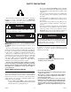
SAFETY PRECAUTIONS • It is also the owner’s responsibility to make certain that the operators and mechanics are qualified and physically able individuals, properly trained in the operation of this equipment. • All operators and mechanics must become familiar with the safe operation of the equipment, operator controls and decals. • Never let children or untrained people operate or service the equipment. Local regulations may restrict the age of the operator.
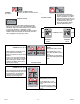
602041 WARNING: Hot surface! Part Number 602041 601967 • Keep a safe distance from the machine. WARNING: Fire! • Clean flammable material from machine. Prevent fires by keeping engine compartment, top of deck, exhaust area, battery, fuel line, fuel tank and operator’s station clean of accumulated trash, grass clippings, and other debris. Always clean up spilled fuel and oil.
DANGER: Battery Hazards! Part Number 601815 601815 • Avoid skin contact with battery acid • Do not overfill battery. • Do not allow open flame near the battery when charging. • Electrolyte may overflow and damage paint, wiring or structure. When clean- • Hydrogen gas forms inside the • ing the battery, use soap and water. Be careful not to get soap and water into the battery. Use soda mixed in water to clean corrosion off the terminals.
Part Number 601981 WARNING: Read Operator’s Manual and decals before attempting to operate this machine. WARNING: Roll over! • Mow a safe distance (minimum of 10 feet) away from drop-offs, retaining walls, drainage ditches, embankments, water, and other types of hazards to avoid a wheel dropping over the edge or to avoid the ground from breaking away. WARNING: Back over! • Do not carry passengers. • Always stop machine if someone enters the area.
Slope Guide Use this diagram when determining the degree of slope to be mowed. E (15o) Slope Guide Lines D (10o) Line B C (5o) Line A 1. 2. 3. 4. 604220 Hold this sheet of paper in front of you. Make sure that Line A is horizontal. Align Line B with a vertical surface such as pole, tree or building. Fold the paper along the slope guide lines (C, D or E). Align the closest slope guide line with the ground slope. This will give you a close estimation of the ground slope to be mowed.
REV C 2-6 604220
OPERATION Safe Operating Practices This product is capable of amputating hands and feet and throwing objects. Always follow all safety instructions to avoid serious injury or death. Safe Operation Evaluate the terrain to determine what accessories and attachments are needed to properly and safely perform the job. Only use accessories and attachments approved by the manufacturer. Never leave a running mower unattended.
Follow the manufacturer’s recommendation for wheel weights or counterweights. If any attachment or additional weight is mounted on the rear of the unit, any rapid movement of the control levers in either direction could result in a reaction of the mower that can cause serious injury. Clean flammable material from mower.
2. Cliffs, retaining walls 3. Roads, highways 4. Buildings 5. Rocks These are just a few examples of situations when caution must be used when operating on a slope. There are many other possibilities too numerous to mention. Just remember to always exercise extreme caution when operating on any slope. Children Tragic accidents can occur if the operator is not alert to the presence of children. Children are often attracted to the mower and the mowing activity.
Control Panel . WARNING A The parking brake may not hold the mower if parked on a slope. Block or chock the machine when parked on a slope. D B. Deck cutting height adjusting lever (Figure 3-4) — the deck cutting height adjusting lever is used to raise or lower the deck. Slide the lever out of a notch and raise or lower the lever and slide it into the desired cutting height notch. B C A. Deck clutch switch B. Ignition switch C. Throttle D.
Engine Starting The mower’s safety start interlock system is also designed to protect the operator and others from accidental injury due to unintentional engine starting. The engine starting motor will not engage until: 1. Steering control levers are in the park brake position. 2. Deck clutch switch is in the down (OFF) position. WARNING Deck cutting height adjusting lever The safety interlock system must not be disconnected or bypassed.
Moving Mower With Stalled Engine Mower Operation If it becomes necessary to move the mower when the engine is inoperative, the transaxles are equipped with bypass valves. Before moving the unit, pull out on the bypass valve rod until the notch in the rod hooks over the edge of the slot. This places the bypass valves in the disengaged position. The valve rod is located per Figure 3-5.
control lever and finish the turn. (Figure 3-7) FRONT OF MOWER FACES THIS DIRECTION WARNING Always be aware of what is behind the machine before backing up. Do not mow in reverse unless absolutely necessary. Always look down and behind before and while backing up. FORWARD TRAVEL N IMPORTANT: Rapid movement of steering control levers is not recommended as damage to the hydraulic system components may occur. To increase speed, increase steering control lever’s distance from neutral.
Operating suggestions THREE POINT TURN DANGER Prior to operating the mower the operator should be thoroughly familiar with the proper use and operation of the equipment, should read the manual completely and thoroughly, and should have attempted slow moving maneuvers to become familiar with the operation of the equipment before attempting normal speed operation. An inexperienced operator should not mow on slopes or on uneven terrain.
have additional sets of blades and change blades twice a day: once in the morning and again at noon. Many problems with incorrect cutting patterns are due to dull blades or blades which have been sharpened incorrectly. Information on sharpening blades is listed in this manual’s maintenance section. In addition, most communities have individuals or companies which specialize in sharpening mower blades. Blade sharpness should be checked daily.
slot, the deck mowing height is set at its lowest mowing position. When the lever is located in the “G” slot, the deck height is at its highest mowing position or transport mode. To adjust the cutting height, slide the deck cutting height adjusting lever out of the notch that it is in and raise or lower it until the desired cutting height is achieved and slide the lever into that notch. Figure 3-9 scalp wheels are designed to minimize scalping when mowing on rough uneven terrain.
MAINTENANCE & ADJUSTMENTS Safe Servicing Practices This product is capable of amputating hands and feet and throwing objects. Always follow all safety instructions to avoid serious injury or death. Service Precautions Unless specifically required, DO NOT have engine running when servicing or making adjustments to mower. Park the machine on level ground.
Inspect mower daily for grass clippings and wire and string tangles. The underside of the mower deck will collect a build-up of grass clippings and dirt, especially when grass is wet or has high moisture content. This build-up will harden, restricting blade and air movement and will probably show a poorer quality of cutting. Therefore it should be removed routinely.
WARNING Incorrect battery cable routing could cause damage to the mower and battery cables. This can cause sparks which can cause a battery gas explosion which will result in personal injury. • Always disconnect the negative (black) battery cable(s) before disconnecting the positive (red) cable(s). • Always connect the positive (red) battery cable(s) before connecting the negative (black) cable(s). Master in-line fuse These mowers have a master in-line fuse in the electrical system.
• Never attempt to start engine when there is a strong odor of gasoline fumes present. Locate and correct cause. • Store fuel in an approved container and keep it out of the reach of children. Never buy more than a 30 day supply of fuel. • Do not fill fuel containers inside a vehicle or on a truck or trailer bed with interior carpets or plastic truck bed liners. Always place fuel containers on the ground away from your vehicle before filling.
5. 6. 7. 8. front of the right side transmission so that it can drain into a suitable oil drain container. With the hose in position, use a 10 mm wrench or socket and open the valve approximately 4 turns in the counterclockwise direction. Allow 10 minutes for engine oil to adequately drain. After oil is drained, close the valve by turning it in the clockwise direction until it is fully closed. Once the valve is closed, carefully remove the oil drain hose and clean up any spilled oil.
WARNING WARNING Never work with blades while engine is running or deck clutch switch is engaged (on). Always place deck clutch switch in the disengaged position, place steering control levers in the park brake position and turn engine off and disconnect negative battery cable. Block up mower when you must work under it. Wear gloves when handling blades. Always check for blade damage if mower strikes rock, branch or other foreign object during mowing! Mower blades are sharp and can cut.
then tighten the cap screws. Cap screw Boss Spindle shaft face Figure 4-9 Steering Control Lever Adjustment The steering control levers can be adjusted for operator comfort. By loosening the cap screws that attaches the upper control lever to the lower lever (Figure 4-10), the upper control lever can be pivoted to fit the operator’s personal preference. The steering control levers can also be adjusted up and down.
Maintenance Schedule Refer to Figure 4-11, Figure 4-12, Figure 4-13, Figure 4-14, & Figure 4-15 WEEKLY OR 40 HOURS SERVICE AT INTERVALS INDICATED ANNUALLY OR 100 HOURS Verify safety start interlock system Prior to each use Visually inspect unit for loose hardware and/or damaged parts Prior to each use Visually inspect tires Prior to each use Check oil level, engine (1) Prior to each use or every 4 hours Clean air intake screen (4) Prior to each use or every 4 hours Check fuel level Prior to ea
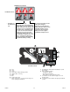
Maintenance Locator Chart Figure 4-11 6 9 2 5 13 8 11 12 3 1. 2. 3. 4. 5. 6. 7. 8. 9. 10. 11. 12. 13. 14. 15. 16.
REV C 4-10 604220
TROUBLESHOOTING The majority of operating problems that occur with a system can be traced to improper adjustments or delayed service. A consistently applied preventative maintenance program, as outlined in the Maintenance section of this manual, will prevent many problems. The following chart is designed to help you locate a problem by suggesting probable causes and the recommended solutions.
REV C 5-2 604220
STORAGE When storing the unit at the end of the mowing season, the mower, engine, and battery should have the following items serviced before storage. If the mower has been stored for an extended period of time, follow the new season preparation steps before beginning operation. General mower preparation for storage 1. Remove all grass, dirt, and trash from mower and cutting units. IMPORTANT: Wash the machine with a mild detergent and water. Do not pressure wash the machine.
PRODUCT LITERATURE If you would like to view or print a copy of the product manuals (Operator’s Manual, Parts Manual, or General Service Manual) for these mowers go online to www.hustlerturf.com and click on the MANUALS button. Contact your local Hustler® dealer if you require another engine manual.
INDEX PAGE PAGE Anti-scalp wheels ..................................................3-10 Mower operation ..................................................... 3-6 Belts .........................................................................4-5 New season preparation ........................................ 6-1 Children ...................................................................3-3 Operating suggestions ........................................... 3-8 Control Panel ..........................