
User Guide
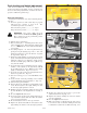


21. Tighten the appropriate nut until the chain just
becomes tight, making sure that the deck stays tight
against the 3" block.
22. Tighten the other nut on the opposite side of the block,
and jam them tightly together against the block.
23. Go to the left rear of the tractor.
24. Make sure that there is still slack in the chain. If not,
loosen the two nuts on the block holding the threaded
rod until there is slack in the deck lift chain. Fig. 5-15
25. Tighten the appropriate nut until the chain just
becomes tight.
26. Tighten the other nut on the opposite side of the block,
and jam them tightly together against the block.
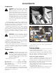
27. Compress the deck lift assist springs so that there is 1”
of space between the front nut and on the spring and
the rear nut on the deck lift block (Fig. 5-19). Typical
both sides.
28. When completed, all chains will be tight, and deck
cutting height will be set to the deck height indicator.
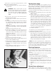
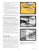
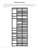
Deck cutting height adjustment
Deck height is adjustable from 1” to 5” (2.54 cm - 12.7
cm) in 1/4” increments. The holes in the height adjusting
bar are spaced at 1/2” intervals. By turning the height
adjusting stop around, 1/4” increments can be attained due
to the 1/4” plate that is part of the stop. Fig. 5-20
EXAMPLE: When the height adjusting stop is placed in
the 1” hole, with the 1/4” plate facing to the front of the
unit, the cutting height is at 1”. When the height adjusting
stop is placed in the 1” hole, with the 1/4” plate on the
operator’s side of the hole, the cutting height is at 1-1/4”.
When the height adjusting stop is placed in one of the
holes, with the 1/4” plate on the operator’s side of the hole,
the deck height will be set at one of the following: 1-1/4”, 1-
3/4”, 2-1/4”, 2-3/4”, 3-1/4”, 3-3/4”, 4-1/4” or 4-3/4”.
When the height adjusting stop is placed in one of the
holes, with the 1/4” plate facing to the front of the unit, the
deck height will be set at one of the following: 1”, 1-1/2”,
2”, 2-1/2”, 3”, 3-1/2”, 4”, 4-1/2” or 5” .
The notch located at the rear of the right height adjusting
bar is to be used when the deck is placed in the transport
mode.
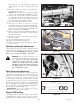
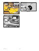
Anti-scalp wheels
Anti-scalp wheel kits are standard on the Hustler ATZ.
These anti-scalp wheels are designed to minimize scalping
when mowing on rough uneven terrain.
After setting the cutting height, adjust the front anti-scalp
wheels so they extend below the deck but do not contact
the ground. They should always be at least 1/4” to 3/4” (.6
cm to 1.9 cm) below the deck. With the unit sitting on a flat
level surface, the front wheel position can be adjusted up or
down as needed from 3/4” to 1-3/4” (1.9 cm to 9.5 cm)
below the blade surface. Move the front wheels up or down,
in 1/2” (1.3 cm) increments, using the different axle mount
holes in the wheel mount bracket. Fig. 5-21
When adjusting the rear anti-scalp wheels, the wheel
should be in the lower axle mount hole when the front anti-
scalp wheels are in the lower or middle axle mount holes.
When the front wheels are in the upper axle mount hole, the
rear wheels should be in the upper axle mount hole as well.
NOTE: When the anti-scalp wheels are installed, the
minimum cutting height is 1” (2.5 cm) with the anti-scalp
wheels set at 3/4”.
397463 1/20/05
5-6
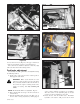
Figure 5-16
Nut
Nut
Chains
Figure 5-17
5/16” bolt
Adjuster
Hardware
Jam nut
Figure 5-18
Foot
pedal
Nuts
Deck lift
threaded rod