
User Guide
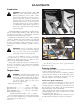
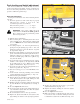


lever to the lower lever (Fig. 5-5), the upper control lever
can be pivoted to fit the operator’s personal preference.
The control levers should be adjusted so that they align
with each other when in the neutral position.
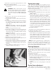
Park brake adjustment
Occasionally check the park brakes and adjustment using
the following method:
1. Position the control levers in the neutral position.
Disengage the deck clutch.
WARNING: Make certain machine is secure
when it is raised and placed on the jack stands.
The jack stands should not allow the machine to
move when the engine is running and the drive
wheels are rotating. Use only certified jack
stands.
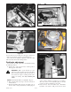
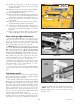
NOTE: The front brake link is not adjustable. Fig. 5-6
2. Raise and block the tractor up so the drive wheels are
off of the floor.
3. Open the hydraulic pump’s bypass valve (Fig. 5-7), on
the side that is being adjusted, by turning bypass
valves counter clockwise one-half to one revolution.
The valve stems on each hydraulic pump are located
near the top and are identified as a hex stud.
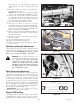
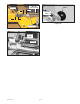
4. Rotate the tire. The tire should rotate. Remember
hydraulic oil resistance will prevent the tire from
Figure 5-7
Bypass valve
Figure 5-6
Front brake link
(right side)
397463 1/20/05
5-3
Figure 5-5
Cap screw
UUppppeerr
ccoonnttrrooll
lleevveerr
Lower control
lever
Figure 5-4
SSpprriinngg
hhoouussiinngg
Front ball
stud
Figure 5-8
1/8”
OOuuttssiiddee eeddggee
CCoonnttrrooll lleevveerr
PPaarrkk bbrraakkee
sslloott