Hustler ATZ Owner’s Manual ••••••• Hustler Turf Equipment ••••• P.O.
WARNING: The engine exhaust from this product contains chemicals known to the State of California to cause cancer, birth defects or other reproductive harm.
TABLE OF CONTENTS 1. General Information.............................................................Sect. 1 2. Safety Precautions................................................................Sect. 2 3. Operation..............................................................................Sect. 3 4. Maintenance .........................................................................Sect. 4 5. Adjustments .........................................................................Sect. 5 6.
GENERAL INFORMATION Warranty registration This manual applies to the following equipment: Hustler ATZ 27/60”, number 927178 Hustler ATZ 27/72”, number 927186 The Delivery and Warranty Registration form must be completed and signed to validate your warranty protection. As the new equipment owner, you are expected to see that the form is completed and forwarded to Hustler Turf Equipment at time of delivery.
HUSTLER ATZ TWO YEAR LIMITED WARRANTY FOR TRACTORS AND DECKS (THREE YEAR LIMITED WARRANTY ON DECK SPINDLE BEARING & DECK GAUGE FORK BEARING) WHAT IS COVERED BY THIS WARRANTY Hustler Turf Equipment, makes the following warranty to the original purchaser only: a. First and Second Year: Hustler Turf Equipment Tractors and Power Units are warranted for two (2) years from date of delivery on all materials and workmanship.
Repairs made by unauthorized persons Damage caused by use of the Hustler Turf Equipment for purposes other than those for which it was designed Damages caused by disasters such as fire, flood, wind, and lightening Damages caused by neglect, abuse, abnormal use, improper or unreasonable use, accident, negligence or misuse Repairs or replacement resulting from the use of unauthorized parts, accessories or attachments Repairs or replacement as the result if any alterations or modifications, in the determinatio
SAFETY PRECAUTIONS operator’s seat. ▲ If you lose steering control while operating the machine, place the steering control levers in the park brake position immediately. Inspect the machine and involve your Hustler dealer to resolve the problem before continuing to operate. ▲ Always remain seated while operating machine. ▲ Always buckle seat belt before starting the tractor. ▲ Always keep safety shields and covers in place, except for servicing.
▲ Data indicates that operators, age 60 years and above, because the machine may tip backward. ▲ When moving in reverse, push forward slowly on lever are involved in a large percentage of riding mowerrelated injuries. These operators should evaluate their ability to operate the mower safely enough to protect themselves and others from serious injury. ▲ Always disengage the blades and wait for them to stop before crossing gravel drives, walks or roads.
The attachments mounted to the tractor will also affect the way it handles on a slope. Be aware that each attachment’s characteristics vary. Another consideration to safe mowing on slopes is to be aware of what is located at the bottom of the slope. Extreme caution should be used when there is a hazard located at the bottom of the slope. Some examples are: 1. Water; i.e. lake, river 2. Cliffs, retaining walls 3. Roads, highways 4. Buildings 5.
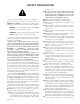
The following illustrations show the various safety decals that are located on the machine. A brief explanation is shown to help the operator understand the meanings of these decals. Do not smoke while refueling. Do not fill tank with engine running, or while the engine is hot. Allow engine to cool before storing machine inside a building. Store away from open flame or spark if there is fuel in tank. Clean up any gasoline spills.
SLOPE GUIDE Use this diagram when determining the degree of slope to be mowed. E (15o) Slope Guide Lines D (10o) Line B C (5o) Line A 1. 2. 3. 4. Hold this sheet of paper in front of you. Make sure that line A is horizontal. Align line B with a verticle surface such as a pole, tree or building. Fold the paper along the slope guide lines (C, D or E). Align the closest slope guide line with the ground slope. This will give you a close estimation of the ground slope to be mowed.
OPERATION 9 12 14 12 Hustler Z Controls 11 10 8 12 17 16 3 5 17 12 7 6 8 1 18 4 2 11 15 12 13 1. 2. 3. 4. Ignition Switch Throttle lever Control levers Deck clutch switch 5. 6. 7. 8. Deck lift pedal Hour meter Oil Pressure light Fuel tanks 9. 10. 11. 12. 13. 12 Hydraulic reservoir Battery Deck adjusting rod Anti-scalp wheels Discharge chute 14. 15. 16. 17. 18.
Control lever in park brake position Hour meter Figure 3-4 Deck lift pedal Figure 3-6 consisting of the park brake switches, seat switch, and deck clutch switch. Check tractor safety start interlock system daily, prior to operation. This system is an important tractor safety feature. It should be repaired immediately if it malfunctions. The machine incorporates a separate seat switch which will stop the tractor engine when the operator is unseated for any reason while the tractor is operating.
WARNING: The safety interlock system must not be disconnected or bypassed. Bypass valve NOTE: The operator’s seat is equipped with a separate safety switch. If for any reason the operator should become unseated when the brake switches are disengaged or the deck clutch switch is engaged the engine will stop. The following steps are the correct procedures for starting the engine. If difficulty is encountered, contact the Hustler Dealer in your area. 1.
FRONT OF TRACTOR FACES THIS DIRECTION N N FORWARD TRAVEL PIVOT TURN FORWARD TRAVEL RIGHT TURN REVERSE TRAVEL RIGHT TURN REVERSE TRAVEL N = Neutral Position Direction of arrows indicate direction of tractor movement. Figure 3-8 Inexperienced operators may have a tendency to oversteer and lose control. Slow-moving practice maneuvers are recommended to become familiar with these characteristics before attempting normal speed operation. To increase speed, increase control lever’s distance from neutral.
individuals or companies which specialize in sharpening mower blades. Blade sharpness should be checked daily. Use high blade speed. Your Hustler Z is designed to operate at full throttle. The throttle setting directly controls blade speed. The highest blade speed generally gives best cut. Direct grass discharge to right, away from unmown area. Select a mowing pattern that directs grass discharge towards the outside, not towards center, of mowing area.
The two post ROPS structure will remain. Fig. 3-10 The weights included with the BAC-VAC™ will be used instead of the ATZ tractor weights. If a BAC-VAC™ is mounted to the ATZ it will be necessary to remove the BAC-VAC™ and front wheel weights from the tractor and it will be necessary to re-attach the drive wheel weights, frame weights and the front and rear mount legs to the tractor before operating the unit on a slope.
MAINTENANCE MAINTENANCE LOCATOR CHART 6 7 14 13 5 13 11 16 3 21 2 12 4 6 1 14 13 13 1. 2. 3. 4. 5. 6. 7. 8. 9. 10. 11. 12. 13. 14. 15. 16. 17. 18. 19. 20. 21.
SERVICE AT INTERVALS INDICATED Verify safety start interlock system Visually inspect unit for loose hardware and/or damaged parts Visually inspect tires Check oil level, engine (1) Clean air intake screen (5) Clean oil heat exchanger (5) Check & clean engine compartment Check air cleaner service indicator(8,9) Check fuel level Blades - sharpen & securely fastened Discharge chute - securely in place & in lowest position Clean engine and pump compartment Replace air cleaner paper element (5) Grease deck idler
correctly torque these items may result in the loss of a wheel or blade, which can cause serious damage or personal injury. Hour meter Torque values given below: Ft-lbs. Nm Wheel (lug) nuts ................................65-75 ......88.14-101.7 Wheel motor nut ............................290-310 .....393.2-420.4 Blade spindle bolt top ........................65-75 ......88.14-101.7 Blade spindle bolt bottom (spindle without blade saddle) ....118 ...........160.
and reproductive harm. Wash hands after handling. Seat platform catch WARNING: Avoid skin contact with battery acid. Always wear eye protection when checking the battery, acid can cause serious injury to skin and eyes. If contact occurs, flush area with clean water and call physician immediately. Acid will also damage clothing. Do not allow open flame near the battery when charging. Hydrogen gas forms inside the battery. This gas is both toxic and flammable and may cause an explosion if exposed to flame.
Fuel tank Cooling fan Heat exchanger Engine Figure 4-7 Figure 4-6 Before applying pressure to hydraulic system, make sure all connections are tight and all hoses and lines are in good condition. To find a leak under pressure, use a piece of cardboard or wood — never use your hands. Relieve all pressure in the system before disconnecting or working on hydraulic lines. To relieve pressure, lower all attachments and shut off engine. The 1.0 U.S. gallon (3.
Pre-cleaner Fuel shut-off valve Figure 4-9 Canister Engine oil drain plug Figure 4-11 Reset button Engine oil filter Figure 4-10 from open flame or spark if there is fuel in the tank. Read and observe safety precautions at front of this manual. Indicator The fuel tanks are located in the tractor’s fenders. (Fig. 4-7) Total capacity for the fuel tanks is 12 U.S. gallon (45.4 liter) Use regular unleaded gasoline with an octane rating of 87 or higher. The fuel filter (Fig.
inclined to disbelieve the need for more expensive air filter elements used on gasoline engines may cause some individuals to opt for a less expensive part. The filter element must be sufficient size and construction to withstand stresses, caused by rapid cycling of the air volume demanded by the engine, without cracking or tearing under fatigue and pressure (especially diesel engines).
2 Viewed from bottom for unit 5 1. Pump belt 2. Engine pulley 3. Pump idler pulley 4. Pump idler arm 5. Pump pulley 6. Electric deck clutch 7. Pump idler spring 1 2 2 5 6 5 3 5 4 4 1 7 2, 6 3 Figure 4-13 Deck Belt Drive Layout Spindle drive belt Deck blade spindle pulley Spindle belt tension idler Spindle belt tension idler spring (9.0" at operation) 5. Deck belt idler 6. Idler arm 1. 2. 3. 4. Figure 4-14 indicate failure, trim ravelings with a sharp knife.
Cutting Edge Warped Blade (Replace) Cutting Plane Twisted Blade Edge (Replace) Cutting Plane Straight Blade Cutting Edge Comparison of Warped and Straight Blades Figure 4-16 Straight Blade Edge Mower blade removal End view of blades, comparing twisted and straighten blades. Use a 15/16" wrench to remove the 5/8" cap screw holding the blade to the spindle shaft from underneath. Sharpen the blades on a grinder following pattern as shown (Fig. 4-15). Touch-up sharpening can be done with a file.
ADJUSTMENTS Introduction Control lever in the neutral position WARNING: Unless specifically required, DO NOT have engine running when servicing or making adjustments to tractor. Place control levers in the park brake position and remove ignition switch key. Repairs or maintenance requiring engine power should be performed by trained personnel only. To prevent carbon monoxide poisoning, be sure proper ventilation is available when engine must be operated in an enclosed area.
Control lever stops If the tractor creeps in the neutral position the control linkage may be adjusted as follows: 1. Raise and block the tractor up so the drive wheels are off of the floor. The control lever stops (Fig. 5-3) are designed to do two things: First, and most important, they must keep the pumps from bottoming out internally. Secondly, the stops may be adjusted to help drive straight when the control levers are pushed forward against the stops.
Spring housing Front brake link (right side) Front ball stud Figure 5-6 Figure 5-4 Upper control lever Cap screw Lower control lever Bypass valve Figure 5-7 Figure 5-5 Control lever lever to the lower lever (Fig. 5-5), the upper control lever can be pivoted to fit the operator’s personal preference. The control levers should be adjusted so that they align with each other when in the neutral position.
5. 6. 7. 8. 9. 10. 11. 12. 13. rotating freely even with the bypass valves open. There should be no resistance from the brakes at this point. Move the control lever to where it is just inside (1/8”) the park brake slot. Fig. 5-8 NOTE: When the control lever is against the outside edge of the the slot, the brakes should not be engaged. Rotate the tire. If the brake is adjusted properly the tire will still rotate but friction will start to become noticeable here.
Deck leveling and height adjustment The mower deck has three areas that may need to be checked and adjusted periodically. Before considering any mower deck leveling adjustments, check that the tire air pressure is within the specified range. Deck level adjustments Leveling the deck must be done in the following manner and order: 1. Check tire pressures to make certain they are properly inflated before starting to level deck. The recommended pressures are as follows: Drive wheels tire pressure..............
21. Tighten the appropriate nut until the chain just becomes tight, making sure that the deck stays tight against the 3" block. 22. Tighten the other nut on the opposite side of the block, and jam them tightly together against the block. 23. Go to the left rear of the tractor. 24. Make sure that there is still slack in the chain. If not, loosen the two nuts on the block holding the threaded rod until there is slack in the deck lift chain. Fig. 5-15 25.
Anti-scalp wheel Deck lift assist springs Lift block 1” Adjusting holes 1” Figure 5-21 Deck lift rod Figure 5-19 Height adjusting stop 1/4” plate Figure 5-20 397463 1/20/05 5-7
TROUBLESHOOTING The majority of operating problems that occur with a system can be traced to improper adjustments or delayed service. A consistently applied preventative maintenance program, as outlined in the maintenance section of this manual, will prevent many problems. The following chart is designed to help you locate a problem by suggesting probable causes and the recommended solutions.
STORAGE Preparation of battery for storage When storing the unit at the the end of the mowing season, the following steps should be taken to ensure readiness for the next mowing season. When the machine is to be unused for long periods, it is best to disconnect the battery and remove it from the unit. At this time perform the following battery maintenance: 1. Clean battery 2. Check the electrolyte level 3. Charge the battery, if necessary 4.
PRODUCT LITERATURE Hydraulic pump information This section contains sources of additional literature concerning your tractor. Literature should be ordered from your Hustler dealer or direct from indicated source. Power to wheel motors is supplied by two Hydro-Gear hydraulic pumps. For more information: Hydro-Gear Customer Services 1411 So.
FREQUENTLY ORDERED PARTS Part No. 027912 027920 783939 781443 781310 784207 068478 747303 782516 783977 785261 Description Lubrizol 7 oz. bottle Lubrizol 10 oz.
Hustler ATZ Parts Manual (P/N 397505) Order Form To order by mail: Fill out this form, fill out the credit card information or attach a check and send it to: Hustler Turf Equipment P.O. Box 808 Hesston, KS 67062 To order by e-mail: Using this form as a guide, send all necessary information, including credit card information to: jhamm@excelhustler.
8-4 397463 1/20/05
TECHNICAL SPECIFICATIONS ENGINE SPECIFICATIONS Horsepower No. of Cylinders Displacement Compression Ratio Max. Torque Kohler 27 2 44.0 CU IN (725 CC) 9.0:1 42.7 FT LBS @ 3000 RPM Starter 12-volt (.
INDEX PAGE Hydraulic pump belt adjustment ......................................5-4 Hydraulic pump information............................................8-1 Hydraulic system..............................................................4-4 Indicators..........................................................................9-1 Instrumentation ................................................................3-2 Lubrication .......................................................................