
User Guide


333559_0806 333559_0806
flame. Always remove the negative ground first and replace
it last.
Do not overfill battery.
Electrolyte may overflow and damage paint, wiring or
structure. When cleaning the battery, use soap and water. Be
careful not to get soap and water into the battery. Clean the
battery terminals with a solution of four parts water and one
part baking soda when they become corroded.
WARNING: Shorts caused by battery terminals or metal
tools touching metal tractor components can cause sparks.
Sparks can cause a battery gas explosion which will result in
personal injury.
Prevent the battery terminals from touching any metal tractor
parts when removing or installing the battery.
Do not allow metal tools to short between the battery
terminals and metal tractor parts.
WARNING: Incorrect battery cable routing could cause
damage to the tractor and battery cables. This can cause
sparks which can cause a battery gas explosion which will
result in personal injury.
Always disconnect the negative (black) battery cable before
disconnecting the positive (red) cable.
Always connect the positive (red) battery cable before
connecting the negative (black) cable.
Common circuit failures are usually caused by shorting, corroded or
dirty terminals; loose connections, defective wire insulation or broken
wires. Switches, solenoids and ignition components may also fail, causing
a shorted or open circuit.
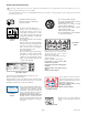
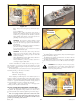
The electrical system is protected by fuses located on the right fuel tank
instrument panel. Fig. 9-3 The fuses are as follows:
Main - 20 amp, blade-type
Clutch/Aux - 10 amp, blade-type
Before attempting any failure diagnosis of the electrical system, use a
test light or voltmeter to check the battery voltage. If the battery voltage is
satisfactory, check the cleanliness and tightness of the terminals and ground
connections. A general understanding of electrical servicing and use of
basic test equipment is necessary for troubleshooting and repair.
Major overhaul or repair of the starting motor or charging system
should be performed by trained technicians only.
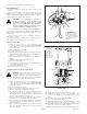
Access to integrated pump/motor transmissions
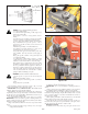
The integrated pump/motor transmissions are accessed by lifting the
seat platform. The seat platform is hinged at the front. To raise it, remove
the lock nut and flat washer and tilt seat platform up and forward. (Fig. 9-
4)
If the seat is equipped with the optional arm rest kit, make certain
to place the control arms in the park brake position and pivot the arm
rests upward before placing the seat platform in the full forward
position to prevent damage to the arm rests.
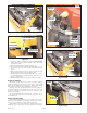
Hydraulic system
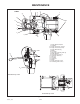
The FasTrak 36/42 is equipped with two Hydro-Gear EZT integrated
pump/motor transmissions. Fig. 9-5
The EZT integrated pump/motor transmissions are sealed for life and
do not require any scheduled service.
The EZT integrated pump/motor transmissions are filled with 20W50
engine oil. If they ever become low on oil, fill to the level shown in Fig. 9-
6.
WARNING: When washing the mower, direct spray away
(especially if using a power washer) from the Hydro-Gear
EZT transmission’s seals to prevent water intrusion and to
ensure component performance.
9-7
Figure 9-2
Battery
Figure 9-4
Lock nut
Flat washer
Figure 9-3
FFuussee
Figure 9-5
EZT integrated
pump/motor