
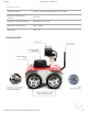
Data Sheet

2/15/2019 ROSbot manual · Husarion Docs
https://husarion.com/manuals/rosbot-manual/#rosbot-manual-overview 8/13
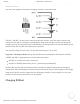
ROSbot is powered from an internal, rechargeable Li-Ion battery pack that contains 3 Li-Ion cells,
connected in series. This type of connection is called “3S”. The schematic below explains how the
cells are wired together and with the charging connector (on ROSbot side).
The BAT+ and BAT- are the power connections and the “bal Bxx” wires are used to monitor the
voltage on each cell. It is strongly recommended to keep equal voltages on each cell during the
charging process. The charger included with ROSbot can charge batteries in the described way and,
thanks to that, the long life of the battery set is possible.
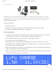
The nominal voltage of each cell is 3.7V but the useful range is 3.2V to 4.2V.
Important - discharge indicator If only the right firmware is preloaded to the internal controller
(CORE2), the LED1 is programmed to indicate the power status:
the LED1 is on when the robot is turned on
the LED1 is blinking when battery is low – please charge immediately!
Please make sure that the user firmware always contains the function that monitors the supply
voltage level. Deep discharging of batteries may decrease their lifecycle. Discharging to the voltage
lower than 3.0V/cell can also trigger the over discharge protection. If the voltage is too low, turn
ROSbot off and charge batteries as soon as possible.
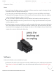
Charging ROSbot
Husarion Docs