
User's Manual


Hunter Industries
1940 Diamond Street • San Marcos, California 92078 • TEL (1) 760-744-5240 • Field Services (800) 248-6561 • FAX (1) 760-591-9582 •
www.hunterindustries.com • www.huntergolf.com
April, 2010
3
output wire should make a three-way connection, with one wire from each of the two solenoids.
Decoder outputs never use a “common” wire.
10. If the decoder is to be ungrounded, fold the bare copper wire
out of the way. If the decoder is to be grounded (every 12
th
decoder or 1000 ft/330m, whichever is first, including last
decoder in the wire path), connect the bare copper
12AWG/2mm dia. ground wire from the decoder to the wire
attached to the appropriate earth grounding hardware, with
a DBR-6 waterproof connector or approved clamp.
Earth Ground: Generally, use an 8’/2.5m rod, or
4”x36”/100mmx1m copper plate (Paige Electric Model
182201 or equal), inserted in the earth in accordance with
the manufacturer’s instructions.
The wire connecting the grounding hardware should be connected
at right angles to the two-wire decoder path, with the ground
hardware at least 8 ft/2.5m away from the two-wire path. There
should be no sharp bends or kinks in the copper ground wire leading to the earth ground hardware. For additional information on earth
grounding in high-lightning environments, consult the American Society of Irrigation Consultants web site, Earth Grounding Guideline
100-2002 (
www.asic.org).
11. Apply controller power and test.
12. Genesis, VSX, and IDS
decoder controllers: Enter
the decoder serial
number(s) to associate
them with a controller
station output. This can be
accomplished from either
the IDSCD software kit, or
directly from the keypad on
these field controllers.
Consult the software or
controller documentation
to complete programming
and testing.
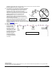
Top View of Decoder Wire Path
Correct
Incorrect