
User's Manual


3.3 Two-Point Compensation
NOTE: To compensate the sensors, both the front and rear sensor on
that side of the vehicle must be mounted, and the longitudinal
toe beam must not be obstructed. Do not rotate one wheel while
the measurements are being saved at the other. The preferred
method is to compensate the sensors separately.
Raise either the front or rear wheels of vehicle.
WARNING: Chock wheels on axle that is not being raised during
compensation to prevent vehicle rolling.
Loosen the sensor lock knobs of all the sensors.
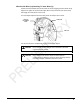
Select any one of the sensors for compensation. The middle LED will be on.
Rotate the wheel adaptor to any desired position. Compensation should preferably begin
(and end) with the wheel adaptor in the vertical position to provide a visual indication that
the vehicle wheel has not rotated.
Snug down the sensor lock knob.
Rotate the wheel until the sensor is level (as indicated by the level on top of the sensor).
Press the compensate button. Do not disturb the sensor until the two outer LED’s begins
to flash and the middle LED turns off indicating that the measurement has been saved.
Loosen the sensor lock knob.
Rotate the wheel clockwise 180° until the middle LED comes on. When the middle LED
is on, snug down the sensor lock knob and rotate the wheel to level the sensor.
Press the compensate button. Do not disturb the sensor. Wait for the sensor to save the
measurement. The two outer LED’s and middle LED will stay on, indicating that the
measurement has been saved and compensation is complete.
Loosen the sensor lock knob.
The sensor is now compensated. Repeat this procedure for the remaining sensor(s).
When using the two-point compensation method, the wheel adaptor must remain in the
same rotational position as it was when its compensation was completed. The middle
LED will be on when the wheel is rotated to the correct position.
NOTE: All sensors should be level, but unlocked (unless directed to
level and lock sensors during the operation sequence) to
minimize tilt of the sensors during caster measurement turn. If
sensors are not locked, then avoid rapid steering motion that
may cause sensors to swing vertically, which can cause them to
come into contact with the rack, or even dislodge from the wheel.
Remove the lock pins from the turning angle gauges and rear slip plates.
Apply the vehicle parking brake and place the transmission in park.
Lower the vehicle onto the turning angle gauges.
Jounce the vehicle.
Two-Point compensation is complete. The middle LED and two outer LED’s on each
sensor will be on.
Continue the alignment procedure.
BETA - WS602 Series Wheel Alignment Sensors Compensating Sensors
• 19