
User's Manual

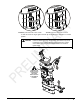


CAUTION: When mounting sensors to the wheel adaptors, the sensor shaft
must be fully seated. Make certain that there is no play or
looseness between the sensor shaft and the wheel adaptor.
Rotate the wheel while holding the sensor. Listen and feel for
movement between the sensor and wheel adaptor. Runout
compensation and alignment accuracy will be adversely affected
if there is any movement between the sensor and wheel adaptor.
Sensors must fit tightly against the surface of the wheel adaptor
or the lock may not hold. This could allow the sensor to fall and
be damaged.
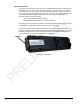
When the sensor is mounted, the sensor locking lever should be rotated using firm hand
pressure. Tools should not be used to force the locking lever. If the lever can be rotated
until it contacts the casting and is not fully locked.
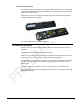
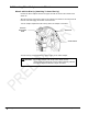
Wheel Adaptor 175-321-1 with Ratchet Adaptor Locking Lever
Rotate locking lever clockwise to tighten. If upper casting prevents rotation of lever, either
expand adaptor to move upper casting or re-position the lever by lifting lever up to
disengage, rotating counter-clockwise, and lowering to re-engage.
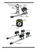
Proceed until the shaft is locked tight to adaptor.
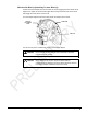
With shaft fully locked, re-position the lever to the 9 o’clock position by lifting lever up to
disengage, rotating to 9 o’clock, and lowering to re-engage.
Re-position lever to 9 o’clock
The lever in the 9 o’clock position eliminates possible contact with upper casting or
sensor during alignments.
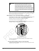
Operation of Ratchet Adaptor Locking Lever after Initial Setup
To remove the sensor or reposition a target, loosen the lock by turning the lever counter-
clockwise to the 3 o’clock position.
12 • Mounting Sensors BETA - WS602 Series Wheel Alignment Sensors