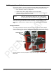
Rhein Tech Laboratories, Inc. 360 Herndon Parkway Suite 1400 Herndon, VA 20170 http://www.rheintech.com Appendix L: Client: Model: Standards: ID’s: Report #: Hunter Engineering Company 45-1281 FCC 15.247/IC RSS-210 LS3-45-1281/2938A-451281 2009249 Manual Please refer to the following pages.
OPERATION INSTRUCTIONS PRELIMINARY Form 6093-T, 09-09 BETA - WS602 Series Wheel Alignment Sensors © Copyright 2009 Hunter Engineering Company
Contents 1. GETTING STARTED..................................................................................3 1.1 About This Manual ..................................................................................................3 1.2 For Your Safety.......................................................................................................3 Hazard Definitions ..................................................................................................3 1.
ii • Contents BETA - WS602 Series Wheel Alignment Sensors
1. Getting Started 1.1 About This Manual This manual contains important operation, maintenance, and safety information for the WS602 Sensors. It is supplemented by the alignment system console operation manual. Read and become familiar with the contents of these publications. A calibrated set of WS602 Sensors can be used with a PA100 series aligner with Pro-Align software version 1.7.2.113 or greater. NOTE: Due to the charging system, only cabinet style aligners may be used.
IMPORTANT SAFETY INSTRUCTIONS Read all instructions. Do not operate equipment with a damaged cord or if the equipment has been dropped or damaged until it has been examined by a qualified service representative. Do not let cord hang over edge of table, bench, or counter or come in contact with hot manifolds or moving fan blades. If an extension cord is necessary, a cord with a current rating equal to or more that that of the equipment should be used.
1.4 XF Pod The WS602 sensors communicate with the aligner console using Extra High Frequency (XF). Radio waves are transmitted and received from the sensors and the XF Pod. Occasionally the XF Pod may receive interference from electronic devices in the neighborhood (microwaves). The WS602 sensors and XF Pod may be configured to use different radio frequencies to minimize interference. The XF system transceiver generates power radio waves in the range of 2.4 GHz.
1.5 Charging Sensor Batteries Each sensor contains a 3.6 VDC 5.2 Amp hour sealed NiMM rechargeable battery pack. To get the maximum life out of the batteries in the sensors, follow these three rules: 1. If the sensors are not in use, charge them. 2. Switch sensors “OFF” during charging if you are using cables. 3. Charge for eleven to thirteen hours, and/or provide an extended charge time (24 hours or longer) at least once a week.
The charge indicator light turning from red to yellow is an indication that the charging mode has switched from a fast charge mode into a “trickle” charge mode. It does not mean that the battery is 100% charged. A fully discharged battery should be allowed to “trickle” charge a minimum of five hours to ensure a full charge. The charge indicator light turns green after approximately 6-8 hours of trickle, indicating the charger has entered “float” mode, which maintains the battery at full charge indefinitely.
Additional information: Any sensor that is powered up after being off for a while will initially indicate 100% capacity on the aligner screen. This is not an accurate indication of the charge state of the battery. The battery has a “surface charge” which dissipates quickly. Within 5 minutes of operation the on-screen battery level indicator will settle at its true value. The individual wheels on the screen indicate the actual battery condition and are color-coded.
User Battery Replacement: The batteries in the battery pack may be replaced. When replacing, use six rechargeable 2700 mAH AA NiMH batteries. Replace all batteries in the battery pack at the same time, with the same type of battery. Remove the six screws securing the assembly. Remove the battery pack top. Replace individual batteries and reassemble. The battery pack must be recharged before use. 1.
1.
2. Mounting Sensors 2.1 Mounting Sensors onto Wheel Adaptors IMPORTANT BETA NOTE: When using this BETA set of WS602 sensors, the long toe arm sensors MUST be mounted in the rear. The sensors will not function correctly if the long toe arm sensors are mounted in the front. Production versions of the sensors will allow for front or rear mounting of the long toe arm sensors, providing the ability to clear front air dams, rear mud flaps, etc.
CAUTION: When mounting sensors to the wheel adaptors, the sensor shaft must be fully seated. Make certain that there is no play or looseness between the sensor shaft and the wheel adaptor. Rotate the wheel while holding the sensor. Listen and feel for movement between the sensor and wheel adaptor. Runout compensation and alignment accuracy will be adversely affected if there is any movement between the sensor and wheel adaptor.
To loosen, turn lever from 9 to 3 o’clock To lock, turn lever from 3 to 9 o’clock To lock the sensor or target, tighten the lock by turning the lever clockwise to 9 o’clock position. CAUTION: Failure to follow tightening and loosening procedures may result in damage to lever. Upper casting can damage lever if contact occurs when going for a large to small diameter rim. Refer to figure below.
2.2 Mounting Wheel Adaptors onto Wheels Wheels with No Rim Lip (Attaching To Outer Rim Lip) Position the wheel adaptor with the two upper external rim studs on the outside of the wheel rim. Align the two lower external rim studs on the outside of the wheel rim and check that all four rim studs will engage the outside of the wheel rim. Turn the adaptor adjustment knob to firmly attach the adaptor to the wheel.
Wheels with Rim Lip (Attaching To Inner Rim Lip) Position the wheel adaptor with the two lower rim studs engaging the lower wheel rim lip. Align the two upper rim studs with the upper wheel rim lip and check that all four studs will engage the inner portion of the rim lip. Turn the adaptor adjustment knob to firmly attach the adaptor to the wheel. ADAPTOR ADJUSTMENT KNOB WHEEL RIM RIM STUD Test the security of the installation by tugging on the wheel adaptor.
16 • Mounting Sensors BETA - WS602 Series Wheel Alignment Sensors
3. Compensating Sensors 3.1 General Compensation The sensors must be compensated to eliminate errors in angle measurements caused by runout of the wheel, wheel adaptor, and sensor shaft. The default setting for the alignment console can be set for either two or three-point compensation. However, the operator still has the option to override the default setting by pressing the “2-Point” or “3-Point” Compensation softkey on the “Compensation Control” screen on the aligner console.
Hand-tighten the sensor lock knob. Rotate the wheel until the sensor is level (as indicated by the spirit level on top of the sensor). Press the compensate button. Do not disturb the sensor until the two outer LED’s begin to blink and the middle LED turns off, indicating that the measurements have been stored. Loosen the sensor lock knob and rotate the wheel 120°, left or right, until the middle LED turns on. Hand tighten the sensor lock knob and rotate the wheel to level the sensor.
3.3 Two-Point Compensation NOTE: To compensate the sensors, both the front and rear sensor on that side of the vehicle must be mounted, and the longitudinal toe beam must not be obstructed. Do not rotate one wheel while the measurements are being saved at the other. The preferred method is to compensate the sensors separately. Raise either the front or rear wheels of vehicle. WARNING: Chock wheels on axle that is not being raised during compensation to prevent vehicle rolling.
3.4 Compensation Recall Mode If sensor power is temporarily interrupted after compensation, a short-term backup memory on the sensor may hold compensation values until power is restored. When power is restored, the sensor will indicate that it has valid compensation values by illuminating the middle compensation indicator while flashing the two outer compensation indicators. If the sensor has not been dismounted from the vehicle wheel, the compensation procedure does not have to be repeated.
4. Operation Information 4.1 Sensor Level Check Procedure To achieve an accurate alignment, it is important that the sensors hang level when the sensor lock knob is loosened. A sensor must be balanced correctly to hang level. To check the balance of a sensor: Mount the sensor on a wheel adaptor. Mount the wheel adaptor onto a wheel without connecting the sensor cable. With the sensor lock knob loosened, wait until the sensor does not rock on the wheel adaptor. Observe the level in the sensor.
22 • Operation Information BETA - WS602 Series Wheel Alignment Sensors
5. Maintenance 5.1 WS602 Battery Replacement Instructions This procedure provides instructions for replacing the battery pack in WS602 wireless sensors. Remove the battery as follows: 1. Depress the upper and lower release buttons on the battery cover and remove. 2. Tilt sensor back and remove battery. Replace the battery as follows: 1. Insert the battery with the positive terminal on top. 2. Replace the battery cover. BATTERY CAP BATTERY TERMINAL 5.
HUNTER RESEARCH AND TRAINING CENTER HUNTER . . . dedicated to service excellence through professional training HUNTER TRAINING - Hunter operates the most advanced, up-to-date Training Center in the industry today. The courses have been designed to meet the needs of new and experienced technicians who want to increase their mechanical and diagnostic capabilities.