
Brochure


56
www.hummel-group.com
www.hummel-group.com
Dimensions and specifications may be changed without prior notice
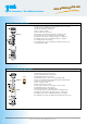
- Straighten the right angle panel connector and screw the base with two panel moun-
ting screws to the panel
- Strip wire ends max. 4 mm (5/32“)
- Solder or crimp the contacts
- Push inserts to the stop in the panel connector. Pay attention to the desired coding
(coding groove, coding key)!
- Fold the spacer around the wires and push it onto the insert
- Close panel connector by folding it 90° and screw the two inner bolts to the panel
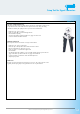
Right Angle Panel Connector
- Strip wire ends 4 mm (5/32“) max.
- Crimp or solder the contacts
- Push the contacts into the inserts
- Fold the spacer around the wires and push it onto the insert
- Push insert and spacer assembly into the housing. Pay attention to the desired coding
(coding groove, coding key)!
- Slide assembly tool onto the housing, through the knurled nut and into the panel
mounted connector
- Tighten the knurled nut and screw the base of the connector to the panel
Panel Connector with knurled Nut
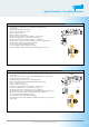
- Attach the housing to the panel. Slip snap ring over the cable
- Strip the cable jacket 20 mm (3/4“). Strip the wire ends 4 mm (.5/32“) max.
Solder or crimp the contacts
Male inserts:
- Push the insert into the housing. Pay attention to the desired coding (coding groove,
coding key). Press the snap ring together slighty and push it into the housing until it
snaps in position.
- Verify proper assembly by pushing on the insert from the opposite side
Female inserts:
- Push the snap ring onto the insert
- Press the snap ring together slightly and push it ino the housing until it snaps in
position. Pay attention to the desired coding (coding groove, coding key)!
- Verify proper assembly by pushing on the insert from the opposite side
Panel Connector Front-, Rear- and Single Hole Mounted
Signal Connectors / Assembly Instructions