
Brochure


54
www.hummel-group.com
www.hummel-group.com
Cod
i
e
rn
ut
3
4
5
7
1
De
t
a
il
A
D
e
t
a
il
B
2
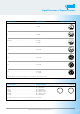
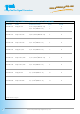
Codiernut
3
4
5
1
6
coding groove
Dimensions and specifications may be changed without prior notice
- Slide dome nut (1), clamping insert (2) and adapter (3) over the cable
- Strip the cable jacket back 20 mm (3/4“)
Shorten the braided shield to 10 mm (3/8“)
- Fold the braided shield over the cable
- Push the EMI ring (4) over the wires onto the braided shield.
Caution: Don’t push the EMI ring behind the braided shield (Detail A)!
- Strip the wire ends 4 mm (5/32“) max.
- Solder or crimp the contacts
- Push the contact into the insert (6)
- Fold spacer (5) around the wires and push it on the insert (6)
- Push the EMI ring (4) onto the spacer (5)
- Fold the braided shield over the EMI ring (4)
- Push insert (6) and spacer (5) assembly into the coupling body (7).
Pay attention to the desired coding (coding groove, coding key)!
- Push adapter (3) onto the coupling body (7) and screw it together
- Push clamping insert (2) into the adapter (3) and tighten the dome nut (1)
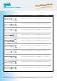
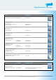
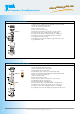
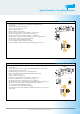
Straight Connector, EMI, Male Thread
Straight Connector, Male Thread
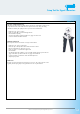
- Slide dome nut (1), clamping insert (2) and adapter (3) over the cable
- Strip the cable jacket back 20 mm (3/4“)
- Strip the wire ends 4 mm (5/32“) max.
- Solder or crimp the contacts
- Push the contacts into the insert (5)
- Fold the spacer around the wires and push it onto the insert (5)
- Push insert (5) and spacer assembly (4) into the bushing (6).
Pay attention to the desired coding (coding groove, coding key)!
- Push adapter (3) onto the coupling body (6) and srew together
- Screw adapter (3) down to the stop
- Push clamping insert (2) into the adapter (3), tighten the dome nut (1)
to grip and seal the cable
Signal Connectors / Assembly Instructions
detail A
detail B
coding groove