06.
TABLE OF CONTENTS Introduction. . . . . . . . . . . . . . . . . . . . . . . . . . . . . . . . . . . . . . . . . . . . . . . . 2 General Information . . . . . . . . . . . . . . . . . . . . . . . . . . . . . . . . . . . . . . . . . Inspection . . . . . . . . . . . . . . . . . . . . . . . . . . . . . . . . . . . . . . . . . . . . . . . . . . . Physical Specification . . .
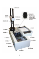
Introduction The Humboldt H-1322B, Marshall and TSR Compression Machine, is a state-of-the-art apparatus specifically designed for Marshall and TSR testing. These tests can be used to evaluate the relative quality of materials, as well as generate input for pavement design or pavement evaluation and analysis. The microprocessor-based system incorporates a 16-bit Analog to Digital (A to D) converter with chart recorder output and RS232 computer connection capabilities.
Physical Specification Net weight: Shipping weight: Overall height: Base dimension: 226 lbs. (110 kg) 266 lbs. (113.6 kg) 39" 35"x18"x10" Power Supply 110 VAC 60 Hz 1 phase (H-1322B), 975 watts 220 VAC 60 Hz 1 phase (H-1322B.2F), 975 watts 220 V AC 50 Hz 1 phase (H-1322B.5F), 975 watts Check that your machine has the correct voltage for your local supply. Power Cord Your Marshall & TSR Test Machine is fitted with a fused IEC receptacle and cord with molded vinyl-grounding plug.
Direction of Travel It is necessary to ensure that the direction of the platen (up or down) has been correctly selected. Choosing one of the three switch positions controls the platen travel direction: Up, Off, or Down. Note: There is a 4 second delay built in between a change in motor direction to allow the motor to stop before restarting in the opposite direction. Maximum Travel Limit Switches Maximum travel limits up and down are indicated on the control panel with green and red indicating lights.
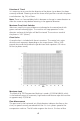
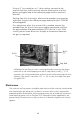
Running a Test 1. Turn on the rear power switch, install a pen in the holder by turning about three turns clockwise with light finger pressure only, and place a sheet of chart paper under the holders. 2. Place the lever in the Pen Down position and zero the pen on the chart with the positioning knobs, placing the pen at the origin of the graduated area of the chart. This will ensure complete recording initiated by sensing of the load.
Using a ½" hex socket on a 3/8" drive ratchet, connect to the internal male hex shaft and crank counter clockwise to raise the platen and apply load to the reference gage and the machine’s load cell. Starting from the chart origin, observe the recorder's pen position and check it against the reference gage reading for each 1000 lbf of load applied.
General Warnings Safety Warnings Operators should take care to operate this machine under the maximum load restrictions. The machine is programmed at the factory to provide safety shutdown if the upper or lower maximum travel is exceeded as well as if the upper instrument calibration is exceeded. Electrical Warnings Typically, there is no reason for the operator to open the machine.
8
Notes 9
Warranty Humboldt Mfg. Co. warrants its products to be free from defects in material or workmanship. The exclusive remedy for this warranty is Humboldt Mfg. Co., factory replacement of any part or parts of such product, for the warranty of this product please refer to Humboldt Mfg. Co. catalog on Terms and Conditions of Sale. The purchaser is responsible for the transportation charges. Humboldt Mfg. Co.