
Installation Instructions
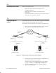
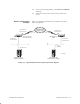
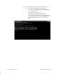
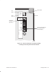
Table Of Contents
- Title page
- Contents
- About this manual
- Safety information
- Ch 1 - Introduction
- Ch 2 - Adding cards to the Controller
- Unpacking the System Controller
- Unpacking the picocells
- System Controller card configuration
- Adding cards to the System Controller (first steps)
- Jumper and DIP switch settings
- Attaching bus cables
- Adding cards to the System Controller (final steps)
- Configuring Controller cards
- Verifying the card configuration
- Ch 3 - Installing the Controller
- Ch 4 - Verifying the Controller configuration
- Ch 5 - Configuring the router
- Ch 6 - Testing picocells
- Ch 7 - Installing picocells
- Ch 8 - Connecting to external equipment
- Ch 9 - System testing
- Ch 10 - Installation inspection
- Ch 11 - Provisioning
- Ch 12 - Remote Client
- Ch 13 - Troubleshooting
- Ch 14 - Maintaining Quad T1 cards
- App A - Specifications
- App B - Standards compliance information
- App C - Part numbers
- App D - Updates and backups
- Index

1026209–0001 Revision B 6–2 Testing picocells
This section explains how to connect a picocell (scanning picocell
or traffic picocell) at the staging area for testing (not for actual
installation).
Test cable: The test cable referred to below is a CAT 5 T1 cable
terminated with RJ–45 connectors at both ends. The cable is
“flipped” so the TX pinouts at one end connect to the RX pinouts
at the other end. (For pinout details, see page 7-12.)
For staging area testing, you connect power from a –48 Vdc power
supply to the test cable, which in turn connects to the picocell.
Connect the scanning picocell first (since it is tested first). Follow
these instructions to connect a scanning picocell or a traffic
picocell:
1. Connect the test cable to the picocell VOICE/DATA IN
(LINE POWER) port, as shown in Figure 6-1.
2. Connect the other end of the test cable to the first Quad T1
card (in slot 9) on the System Controller. See Figure 6-2:
- For a scanning picocell, connect to the second port
(from the top) of the first Quad T1 card.
- For a traffic picocell, connect to the third port (from
the top) of the first Quad T1 card.
CAUTION
Make sure the picocell power switch is OFF
(middle position) before connecting the
picocell to the Controller.
6.1
Connecting a
picocell for testing